Control systems and methods for thermal-jet printing

a control system and thermal-jet printing technology, applied in printing, typewriters, electrical devices, etc., can solve problems such as difficulty in making and manufacturing with consistent quality and performance using conventional techniques

Inactive Publication Date: 2012-03-08
KATEEVA
View PDF6 Cites 75 Cited by
  • Summary
  • Abstract
  • Description
  • Claims
  • Application Information

AI Technical Summary

Benefits of technology

[0011]The heating element, according to various embodiments, is configured to cycle the discharge nozzle through a heating profile that deposits the print material of the ink onto a suitable substrate (e.g. glass). For example, the heating element heats the discharge nozzle to remove or evaporate the carrier liquid from the ink...

Problems solved by technology

While OLEDs have shown great promise for replacing more conventional displays, currently they can b...

Method used


Image

  • Control systems and methods for thermal-jet printing
  • Control systems and methods for thermal-jet printing
  • Control systems and methods for thermal-jet printing

Examples


Embodiment Construction

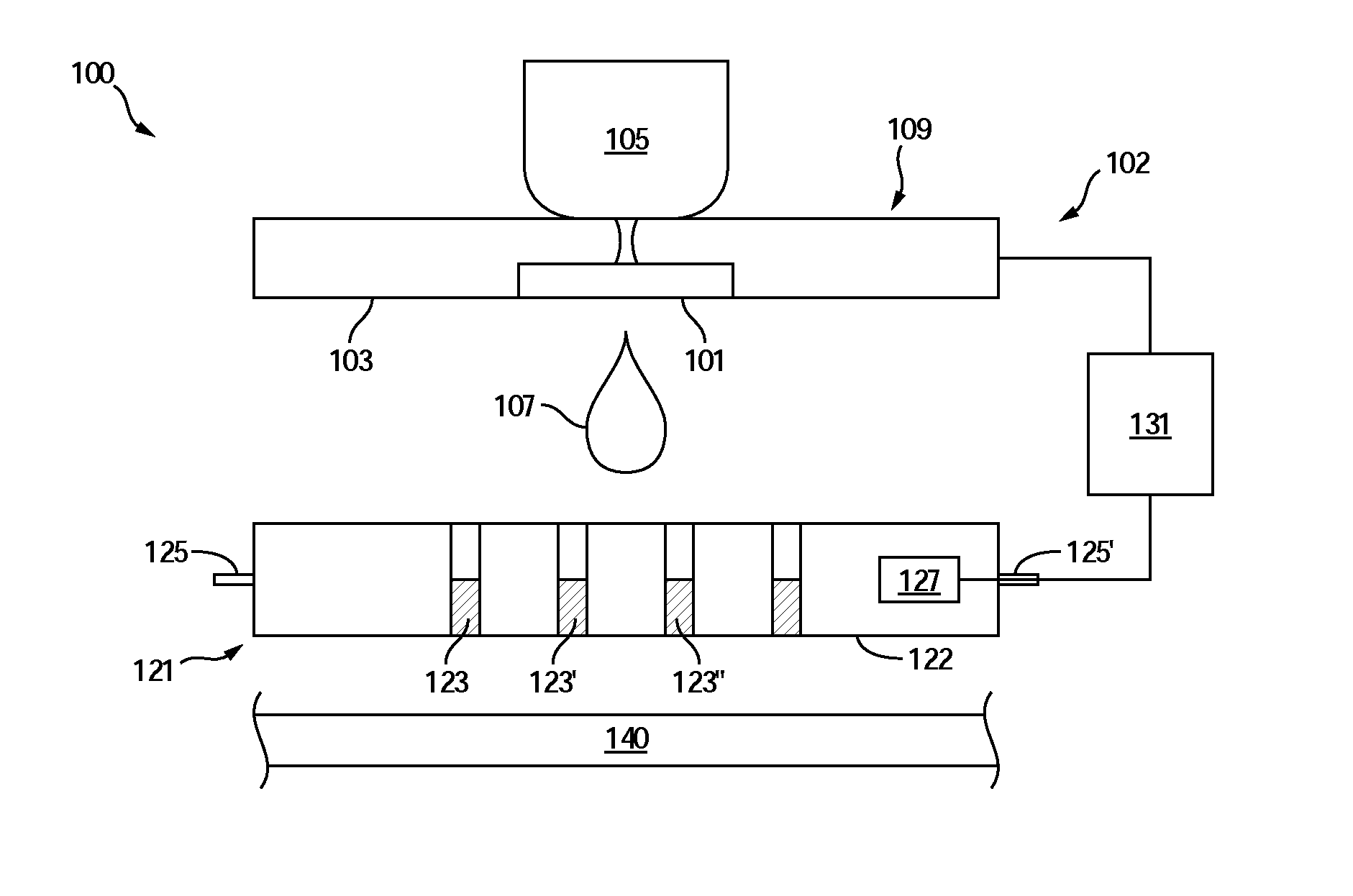
[0022]Referring to FIG. 1, various aspects of the present teachings are directed to a printing apparatus, such as printing apparatus 100 that includes a printhead 102. The printhead 102 includes a dispensing mechanism 109 for dispensing droplets of ink 107. The dispensing mechanism 109 can be an ink-jet with support structure 103, a controlled dispensing nozzle 101 and an ink reservoir 105 coupled to the controlled dispensing nozzle 101.

[0023]The printhead 102 further includes a thermal-jet 121 with a discharge nozzle 122 and heating element 127. The discharge nozzle 122 is formed from any suitable material or combination of materials, such as described above and is patterned with micro-structures 123, 123′ and 123″. The thermal-jet 121 is positioned in proximity with the dispensing mechanism 109 for receiving the droplets of ink 107, such that ink enters the micro-structures 123, 123′ and 123″, as indicated by the hatching within the micro-structures 123, 123′ and 123″.

[0024]The mi...


PUM


Abstract

Embodiments of methods and apparatus for micro-printing films are disclosed. According to various embodiments, the printing apparatus includes printheads with ink-jets for dispensing droplets of ink formed from a carrier liquid and a print material. The printheads also include thermal-jets for depositing the print material onto a substrate from the droplets of ink dispensed by ink-jets. The droplets of ink dispensed by ink-jets flow into micro-structures on the thermal-jets and the thermal-jets are heated to evaporate the carrier liquid and to vaporize and direct the print material onto a substrate. The printing apparatus further includes a control unit that is configured to automatically adjust an output from one or more printheads based on one or more measured quantities.

Description

RELATED APPLICATION[0001]This application is a Continuation-in-Part Application of the co-pending U.S. patent application Ser. No. 12 / 580,831, titled “METHOD AND APPARATUS FOR CONTROLLING THE TEMPERATURE OF AN ELECTRICALLY-HEATED DISCHARGE NOZZLE”, filed Oct. 16, 2009, which claims priority under 35 U.S.C. 119 (e) of the U.S. Provisional Patent Application Ser. No. 61 / 142,575, filed Jan. 5, 2009, and titled “METHOD AND APPARATUS FOR CONTROLLING THE TEMPERATURE OF AN ELECTRICALLY-HEATED DISCHARGE NOZZLE”. This patent application also claims priority under 35 U.S.C. 119 (e) of the U.S. Provisional Patent Application Ser. No. 61 / 509,042, filed Jul. 18, 2011, and titled “CONTROL SYSTEMS AND METHOD FOR THERMAL-JET PRINTING”. The co-pending U.S. patent application Ser. No. 12 / 580,831, titled “METHOD AND APPARATUS FOR CONTROLLING THE TEMPERATURE OF AN ELECTRICALLY-HEATED DISCHARGE NOZZLE”, filed Oct. 16, 2009, the U.S. Provisional Patent Application Ser. No. 61 / 142,575, filed Jan. 5, 2009,...

Claims


Application Information

Patent Timeline
IPC IPC(8): B41J29/38
CPCB41J2/0456B41J2/04565B41J2/0458B41J2/0459B41J2/14H01L51/0005B41J2/195B41J2/2142B41J3/407B41J2202/09B41J2/175H10K71/135
Inventor VRONSKY, ELIYAHUGASSEND, VALERIEGOLDA, DARIUSZKIM, HYEUN-SU
Owner KATEEVA
Why Eureka
Try Eureka