Compressor blade root for engine blades of aircraft engines

a compression blade and engine technology, applied in the direction of machines/engines, electrochemical machining apparatus, climate sustainability, etc., can solve the problem that the fiber-composite core cannot stand up to the force, and achieve the effect of reducing the bending load of the fiber material, high force and favorable operation

Inactive Publication Date: 2005-04-21
ROLLS ROYCE DEUT LTD & CO KG
View PDF12 Cites 52 Cited by
  • Summary
  • Abstract
  • Description
  • Claims
  • Application Information

AI Technical Summary

Benefits of technology

[0007] It is a broad aspect of the present invention to provide an engine blade whose compressor blade root features a fiber-composite core and a metallic enclosure such that the blade is capable of taking up and transferring high forces while having a long service life.
[0010] This fiber-composite core enables, on the one hand, high forces to be taken up and transferred to the enclosure in the area of the blade root, i.e. introduced in the metallic part of the blade root. On the other hand, the bending load of the fiber material is reduced by the frictionally dampened pendular movement of the blade root allowed within a limited range in the recess of the compressor disk.
[0011] A compressor blade featuring such a compressor blade root is very light, which is favorable for the operation of the gas turbine engine. Such a compressor blade is nevertheless capable of withstanding and transferring, without damage, the high forces to which it is exposed. It has high dynamic strength and fatigue stability, as well as a long service life. Stress and wear in the recess locating the blade root are reduced.

Problems solved by technology

Since this design of a fiber-composite core is not capable of withstanding high bending loads, it is pendularly located within a limited angular range and frictionally dampened in the recess for the location of the blade root in the compressor disk.

Method used


Image

  • Compressor blade root for engine blades of aircraft engines
  • Compressor blade root for engine blades of aircraft engines

Examples


Embodiment Construction

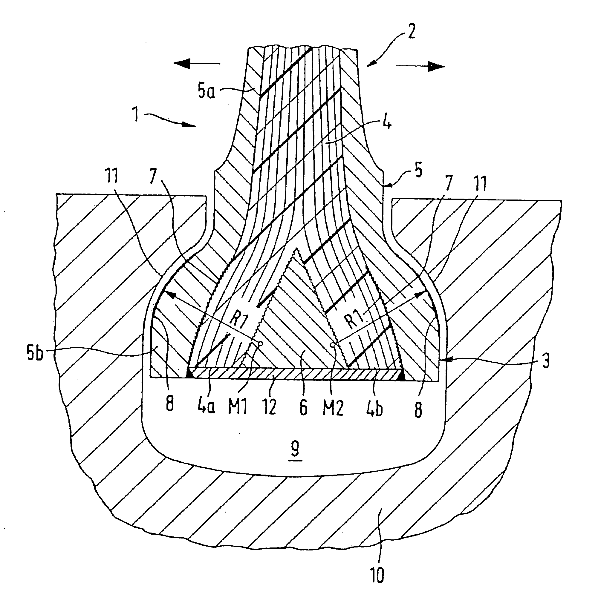
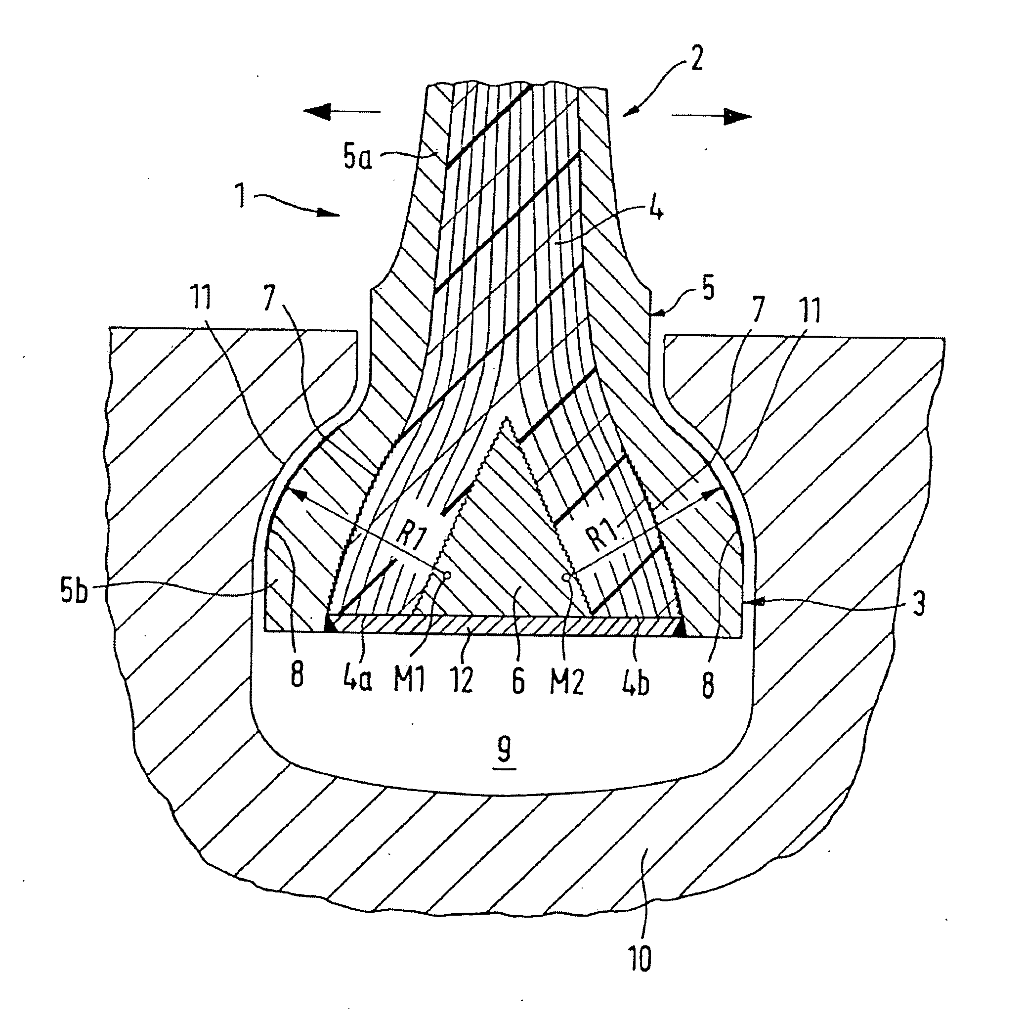
[0014] The compressor blade 1 comprises an airfoil 2 and a blade root 3 and includes a fiber-composite core 4 and a metallic enclosure 5 with a thin-walled portion 5a in the area of the airfoil 2 and with a thick-walled portion 5b in the area of the blade root 3. In the blade root 3, a reinforcing wedge 6 divides the fiber-composite core 4 into two partial strands 4a, 4b to provide for high strength in the root area and to enable the high tensile forces acting upon the airfoil 2 to be effectively introduced into the blade root 3. Upon infiltration, a metal plate 12 is attached (for instance, by welding or other means) at the bottom end of the blade, preferably to the reinforcing wedge, to take up the clamping forces produced by the centrifugal loads and, thus, to reduce the mechanical pressure load on the carbon fibers.

[0015] Preferably, a large end of the wedge 6 is positioned below a fit of the blade root 3 to the compressor disk 10 to avoid delamination forces under centrifugal ...


PUM

PropertyMeasurementUnit
bending stressaaaaaaaaaa
pressureaaaaaaaaaa
areaaaaaaaaaaa

Abstract

On a compressor blade (1) for gas turbine engines which is made of a fiber-composite core (4) with metallic enclosure (5) and which comprises a blade root (3) connected to an airfoil (2) and held in a recess (9) of a compressor disk (10), the fiber-composite core is made of transversely compressed fibers with subsequent matrix infiltration and is intimately connected via a surface enlargement by a micro-structure (7) to inner surfaces of the enclosure (5). Thus, the forces are introduced into the blade root (3) directly via the fiber material. Opposite side faces of the longitudinally straight blade root (3) each feature circularly arched bearing faces (8) with different centers (M1, M2) which mate with similarly arched bearing areas (11) provided in the recess (9) to provide for a limited, dampened pendular movement for the absorption of the bending forces acting upon the fiber-composite core.

Description

[0001] This application claims priority to German Patent Application DE10326719.0 filed Jun. 6, 2004, the entirety of which is incorporated by reference herein. BACKGROUND OF THE INVENTION [0002] This invention relates to a compressor blade root for engine blades of aircraft engines which comprise a fiber-composite core with metallic enclosure and which is held in a recess of a compressor disk. [0003] In order to save weight, the fan blades (compressor blades) of gas turbine engines are, as is generally known, made of fiber-reinforced plastic with a metallic enclosure. The blade is firmly attached via a dovetail-style, longitudinally curved blade root in a conformal recess of the compressor disk (rotor). Centrifugal forces, gas pressure and vibrations of the airfoil excited by the flow medium subject the compressor blades of turbomachines to considerable stresses which, in the case of aircraft engines, can become excessive in the event of a bird strike, i.e. an impingement of a bird...

Claims


Application Information

Patent Timeline
Patent Type & Authority Applications(United States)
IPC IPC(8): B23H3/00B23H3/04B23H9/00B64C11/04B64C11/26C23C14/00C25B9/00F01D5/14F01D5/28F01D5/30F04D29/34
CPCF01D5/282F01D5/30Y02T50/672F04D29/34F04D29/023B23H3/00B23H3/04B23H9/00B23H9/006F05D2230/80Y02T50/60
Inventor SCHREIBER, KARL
Owner ROLLS ROYCE DEUT LTD & CO KG
Why Eureka
Try Eureka