Variable Extension Spring For Orthodontics

Inactive Publication Date: 2012-03-08
ALLESEE TIMOTHY J
24 Cites 10 Cited by

AI-Extracted Technical Summary

Problems solved by technology

Tooth movement eventually ceases, as the spring no lo...

Benefits of technology

[0013]Each anchoring mechanism comprises at least one engagement mechanism, such as an eyelet. Other suitable engagement mechanisms known to one skilled in the art, such as hooks, may also be used. At least one of the anchoring mechanisms comprises more than one engagement mechanism. Each engagement mechanism is disposed at an engagement position.
[0014]In use, the orthodontist identifies an engagement position, which when engaged with a post on a bracket for example, exerts a desired level of force to pull teeth towards each other. As the teeth move toward each other over time, the original distance the spring is stretched decreases. Tooth movement eventually ceases, as the sp...

Abstract

A variable extension spring with two anchoring ends. Each anchoring end connected to an anchoring mechanism having engagement mechanisms. Engagement mechanisms may be eyelets. Engagement of the engagement mechanisms to intraoral features at different engagement positions allows variability in the extension length of the spring. Such variability allows the user to adjust the force exerted by the spring on the intraoral features. As intraoral features move overtime due to the force exerted by the spring, the extension length of the spring may change. Adjustment of the spring extension length is accomplished by engaging a different engagement mechanism to provide an engagement position that will extend the spring the desired length. The user is able to reduce inventory by being able to use the same spring several times to provide a desired range of forces for adjusting orthodontia.

Application Domain

Arch wiresDental tools

Technology Topic

Engineering

Image

  • Variable Extension Spring For Orthodontics
  • Variable Extension Spring For Orthodontics
  • Variable Extension Spring For Orthodontics

Examples

  • Experimental program(1)

Example

[0030]While this invention is susceptible of embodiment in many different forms, there are shown in the drawings, and will be described herein in detail, specific embodiments thereof with the understanding that the present disclosure is to be considered as an exemplification of the principles of the invention and is not intended to limit the invention to the specific embodiments illustrated.
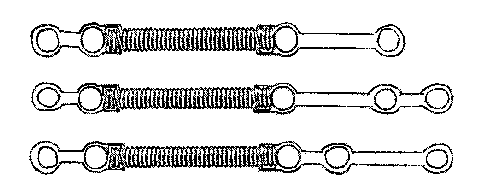
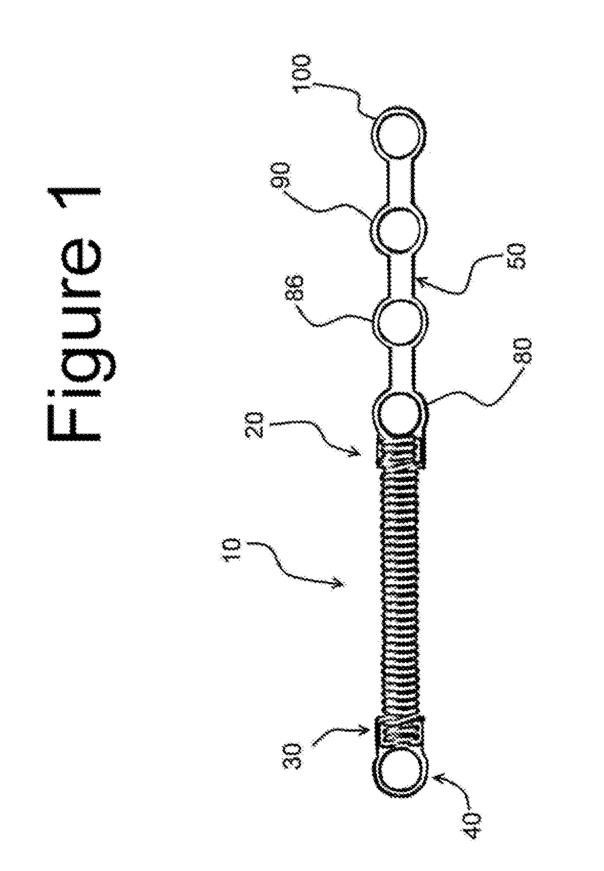
[0031]FIG. 1 illustrates an exemplary embodiment of the variable extension spring. The variable extension spring comprises a coil spring 10, with two anchoring ends 20, 30. The two anchoring ends 20, 30 are respectively attached to anchoring mechanisms 40, 50.
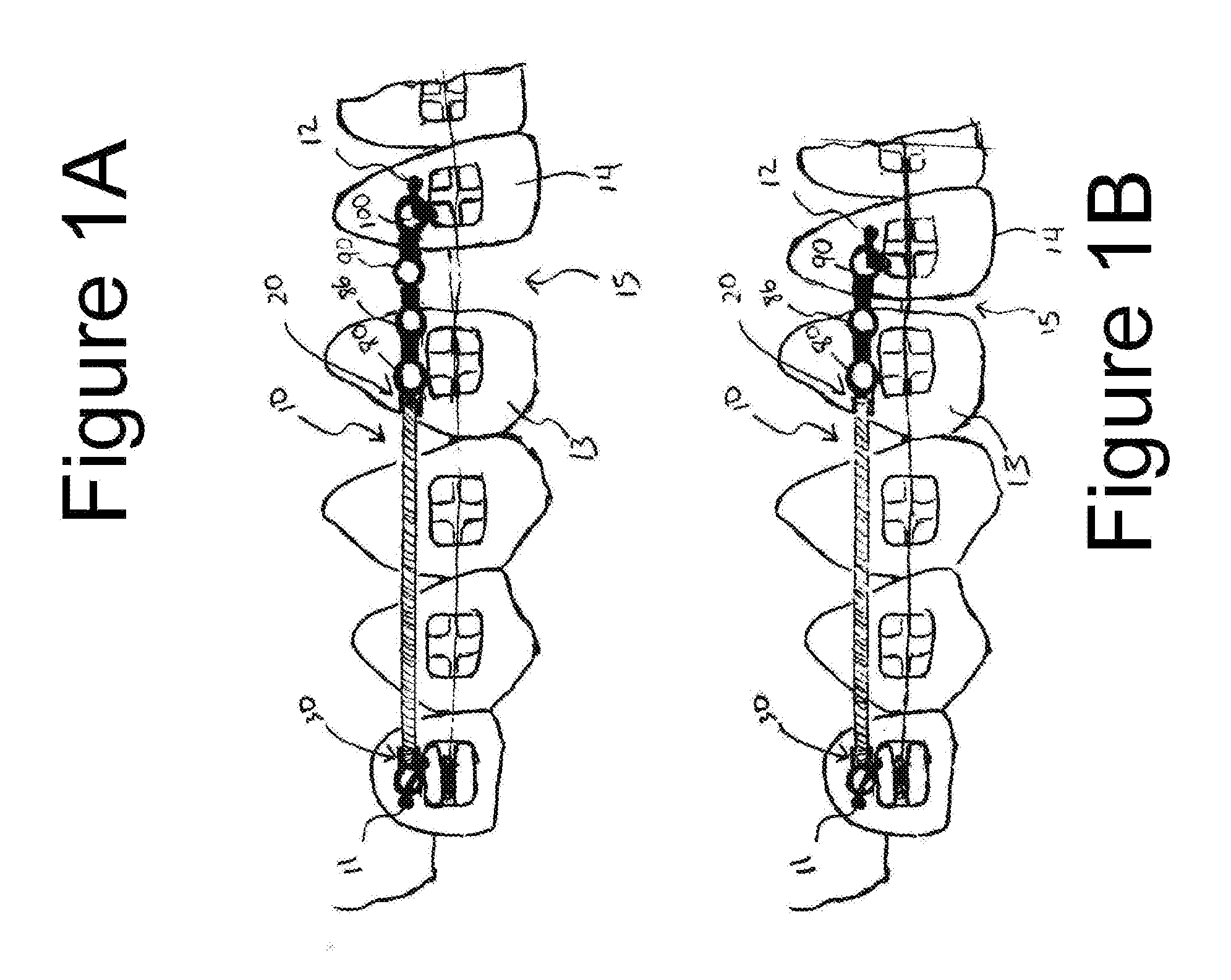
[0032]The anchoring mechanism 50 comprises engagement mechanisms 80, 86, 90, 100. Anchoring mechanism 60 as illustrated in FIG. 3 comprise engagement mechanisms 80, 90, 100. At least one of the anchoring mechanisms comprises more than one engagement mechanism. FIG. 1A illustrates the variable extension spring of FIG. 1 extended between two anchors 11, 12 in a patient's mouth to move teeth 13, 14 towards each other.
[0033]The coil spring 10 may configured as be a tension spring or a compression spring. The coil spring may be made of stainless steel, nickel titanium, beta titanium, or other suitable alloys which provide adequate shape memory. Coil springs of various expansion capabilities, such as 6 mm, 9 mm, and 12 mm springs, may be used to exert the desired force on teeth. This generally depends on the span between teeth to be moved or the desired amount of space closure required for successful completion of the procedure. Each anchoring end 20, 30 of the coil spring 10 is connected to an anchoring mechanism at its spring attachment region 70 (FIG. 3).
[0034]FIG. 3 illustrates an anchoring mechanism 60. The anchoring mechanism 60 may be made from the same or different material as the coil spring. The anchoring mechanism 60 can be made from ductile material, such as 304 or 302 series stainless steel that can be cut using dental cutting instruments. The anchoring mechanism 60 comprises a spring attachment region 70, and at least one engagement mechanism 80, 90, 100. The spring attachment region 70 can comprises two channels 71, 72 spaced a distance “S” apart (FIG. 5), through which the anchoring ends of the coil spring is wound to attach the anchoring mechanism to the anchoring end of the coil spring. The channels 71, 72 are spaced apart a distance S such that the coil radius at the anchoring ends 25, 35 (FIG. 6) is consistent with the coil radius at the body 45 of the coil spring 15. Alternatively, the channels can be spaced a distance S apart such that the radius of the coil at the anchoring end when wounded though the channels 71, 72, is greater or smaller than the radius of the body of the coil spring. Other types of spring attachment regions known to one skilled in the art can also be used to connect the anchoring ends of the coil spring to the anchoring mechanisms. For example, as illustrated in FIG. 4, the spring attachment region can comprise a hole 115 and notches 110a, 110b for attachment to an anchoring end of the coil spring. In another embodiment, the spring attachment region allows the anchoring mechanism to rotate about an axis parallel to the longitudinal axis of the coil spring. The anchoring mechanism may rotate about an axis in line with the longitudinal axis of the coil spring. Anchoring ends 25, 35 of the spring may be engaged to allow the anchoring mechanism and the coil spring to swivel with respect to each other. Alternatively, in yet another embodiment, the spring attachment region allows for the anchoring ends 25, 35 to engage with the anchoring mechanism such that the anchoring mechanism may rotate about an axis perpendicular to the longitudinal axis of the coil spring.
[0035]In the embodiment illustrated in FIG. 3, the spring attachment region 70 extends from an adjacent engagement mechanism. The anchoring mechanism comprises three engagement mechanisms 80, 90, 100. The engagement mechanisms can be eyelets as illustrated, or may be any other suitable engagement mechanism such as a bracket, hook or eyelets of various shapes or internal diameters. In use, each engagement mechanism 80, 90, 100 provides a corresponding engagement position. For example, engagement mechanism 100 provides a first engagement position, and engagement mechanism 90 provides a second engagement position. The engagement mechanisms illustrated in FIG. 3 are spaced equidistant from each other, with bridges 130a, 130b connecting the engagement mechanisms 80, 90, 100 in series. Alternate arrangements for the engagement mechanisms are illustrated in FIGS. 2A-2E. FIG. 2A illustrates a variable engagement spring comprising two engagement mechanisms on one of the anchoring mechanisms. FIG. 2B illustrates embodiment of the variable extension spring comprising three non-equidistantly disposed engagement mechanisms on one of the anchoring mechanisms. FIG. 2C illustrates a variable extension spring with at least two engagement mechanisms on each anchoring mechanism. FIG. 2D illustrates a variable extension spring comprising three engagement mechanisms on each anchoring mechanism. FIG. 2E illustrates a variable extension spring comprising differently sized engagement mechanisms. A larger engagement mechanism 85 may be used on one side of the coil spring to adapt for use with a temporary anchoring device or TAD (not shown). In one embodiment, the larger engagement mechanism 85 can have an inner diameter of 0.088″ (2.235 mm), and an outer diameter of a suitable size to appropriately engage with the TAD.
[0036]In another embodiment, as illustrated in FIG. 5, the anchoring mechanism may be about 0.01″ (0.254 mm) in thickness, with an inner eyelet diameter of 0.058″ (1.473 mm), and an outer eyelet diameter of 0.088″ (2.235 mm).
[0037]The bridge portions 130a, 130b span a distance “L” as illustrated in FIG. 3. Distance L should be of a sufficient length to allow for a cutting instrument to be positioned between two adjacent engagement mechanisms, such that the engagement mechanism(s) furthest away from the coiled spring may be disconnected from the rest of the anchoring mechanism when the engagement position(s) is no longer needed, but may also be of a shorter or longer distance.
[0038]In the alternative embodiment illustrated in FIG. 4, the engagement mechanism uses a hook-type mechanism 125a, 125b. The anchoring mechanisms can comprise one row of engagement mechanisms 125a, or may have engagement mechanisms aligned in a pair of offset rows 120a, 120b, such that more engagement positions are provided within the same distance span “D”. Additional alternative embodiments, illustrated in FIGS. 4A, and 4B show that the engagement mechanisms can be any shape, including non-symmetrical shapes, to better accommodate the various types of hooks or TAD's. FIG. 4A illustrates an anchoring mechanism 135 with diamond-shaped engagement mechanisms 140 on one end of a coil 145 having an anchoring mechanism 136 on the opposite end comprising a circular eyelet 141. FIG. 4B illustrates an anchoring mechanism 137 with an oblong eyelet 150 on one end of a coil 155 having an anchoring mechanism138 on the opposite end comprising a circular eyelet 151.
[0039]In use, an orthodontist selects a variable extension spring with the appropriate coil spring expansion capability and anchoring mechanism to provide an appropriate number and spacing of engagement mechanisms. The location of the engagement mechanism corresponds to engagement positions which provide predetermined increments of force. For example, engaging an outermost engagement mechanism 100 in FIG. 1 will exert less force on teeth than engaging the engagement mechanism 90 immediately adjacent. An orthodontist may select the correct engagement mechanism with which to begin treatment, and simply detach, if any, outer engagement mechanisms beyond the engagement mechanism selected. Alternatively, an orthodontist may select a variable extension spring wherein the outermost engagement mechanism 180 corresponds to the correct engagement position to provide the desired force. The distance between engagement mechanisms is also selected by the orthodontist in anticipation of the gradual movement of teeth as a result of the force of the spring exerted on the teeth between visits to the orthodontist office. As illustrated in FIG. 1A, a variable extension spring with engagement mechanisms 80, 86, 90, and 100 is selected for use. The anchor 12 on teeth 14 engages with the outermost engagement mechanism 100. Engagement mechanism 90 is adjacent to engagement mechanism 100.
[0040]As treatment progresses, the force exerted by, for example, a tension spring such as the one illustrated in FIG. 1A, causes teeth to move closer. As teeth move toward each other, the extension length, and correspondingly the force exerted by the spring on the teeth, decreases. A patient returns at the next appointment to readjust the spring to exert a desired force, such as the one provided by the adjacent engagement mechanism 90, as illustrated in FIG. 1B. Engagement mechanism 100 is removed by the orthodontist, leaving engagement mechanism 90 as the outermost engagement mechanism. Switching to engagement mechanism 90 for use with the anchor 12 allows more force to be exerted on the teeth 14 than engagement mechanism 100 in light of the movement of the teeth 14 over time, as indicated by the narrower gap 15 between teeth 13 and 14 in FIG. 1B as compared to FIG. 1A.
[0041]By having the anchoring mechanism provide more than one engagement position by way of having multiple engagement mechanisms, the orthodontist is able to adjust the force exerted on adjacent teeth by selecting a different engagement position, without having to replace the entire spring. The orthodontist is also able to select a variable extension spring that provides a suitable distance between the engagement mechanisms based on the force exerted by the spring and the anticipated movement of the teeth as a result of the force exerted by the spring on the teeth, to determine the time needed between visits to readjust the engagement mechanism. Alternatively, if a patient desires a certain time frame in the future for a next visit, the orthodontist may select a variable extension spring based on the factors above, to suit the patient's schedule. The demonstrated versatility of the variable extension spring allows for the user to reduce inventory, as a wider range of functions are able to be addressed with a fewer number of springs. Furthermore, time spent by the orthodontist adjusting the force exerted on the spring is decreased as the orthodontist need only disengage the previous engagement mechanism, and select a second engagement mechanism to provide the engagement position with the desired force. The user can then remove, by cutting, the engagement mechanism that provided the first engagement position, or the engagement mechanism beyond which engagement positions are no longer useful to provide the desired force.
[0042]Some specific types of nickel titanium coil springs exhibit “superelastic” properties versus the more common variable force properties. Superelasticity denotes a relatively constant force regardless of the range of extension. Superelastic springs may, however, lose these properties if they are overextended. Superelastic springs will also lose their ability to move teeth once they return to or near their original shape. Conventional superelastic springs cannot be “reactivated” via multiple eyelets to overcome these limitations. However, having multiple eyelets for use with coil springs made of superelastic material provides the user with the benefit of reducing inventory. An orthodontist has the option of selecting the appropriate engagement mechanism with which to begin treatment, and simply detach, if any, outer engagement mechanisms beyond the engagement mechanism selected. Inventory is reduced because one variable extension spring can provide the orthodontist multiple extension distances from which a distance for beginning treatment can be selected.
[0043]From the foregoing, it will be observed that numerous variations and modifications may be effected without departing from the spirit and scope of the invention. It is to be understood that no limitation with respect to the specific apparatus illustrated herein is intended or should be inferred.

PUM

no PUM

Description & Claims & Application Information

We can also present the details of the Description, Claims and Application information to help users get a comprehensive understanding of the technical details of the patent, such as background art, summary of invention, brief description of drawings, description of embodiments, and other original content. On the other hand, users can also determine the specific scope of protection of the technology through the list of claims; as well as understand the changes in the life cycle of the technology with the presentation of the patent timeline. Login to view more.

Similar technology patents

Gasket for a camera lens, and multi-headed camera

ActiveUS20190368613A1decrease distancereduce reflection of light
Owner:MOTOROLA SOLUTIONS INC

Golf club head

ActiveUS20110130215A1decrease distance
Owner:BRIDGESTONE SPORTS

Near-field electron laser

ActiveUS20180248331A1radiation intensity and directionality of be enhancedecrease distance
Owner:GONG BINGXIN

Access Panels

ActiveUS20140259949A1decrease distanceincrease distance
Owner:HOME DEPOT PROD AUTHORITY

Mask having assist pattern

ActiveUS20130316270A1increase thicknessdecrease distance
Owner:SAMSUNG DISPLAY CO LTD

Classification and recommendation of technical efficacy words

  • decrease distance

Radiation image pickup apparatus and its control method

InactiveUS20050264665A1decrease distanceimprove S/N ratio
Owner:CANON KK

Mobile terminal and display controlling method thereof

InactiveUS20110061021A1adjustable in sizedecrease distance
Owner:LG ELECTRONICS INC

Flat plate heat transfer device

InactiveUS20070107875A1decrease distancemaximize heat transfer performance
Owner:LS MTRON LTD

Layered visualization of content representations

ActiveUS9098167B1quickly and easily determinedecrease distance
Owner:QURIO HLDG
Why Eureka
Try Eureka