Surfer lift system

Inactive Publication Date: 2006-07-27
MKS ENTERPRISES
View PDF10 Cites 0 Cited by
  • Summary
  • Abstract
  • Description
  • Claims
  • Application Information

AI Technical Summary

Benefits of technology

[0006] The initial distance, i.e., the distance the rider is suspended below the cable before any lowering toward the water, can be set to carry the rider high enough to pass over the crests of the waves. In some embodiments, the

Problems solved by technology

Few skiers would consider engaging in their sport without the benefit of pow

Method used


Image

  • Surfer lift system
  • Surfer lift system
  • Surfer lift system

Examples


Example

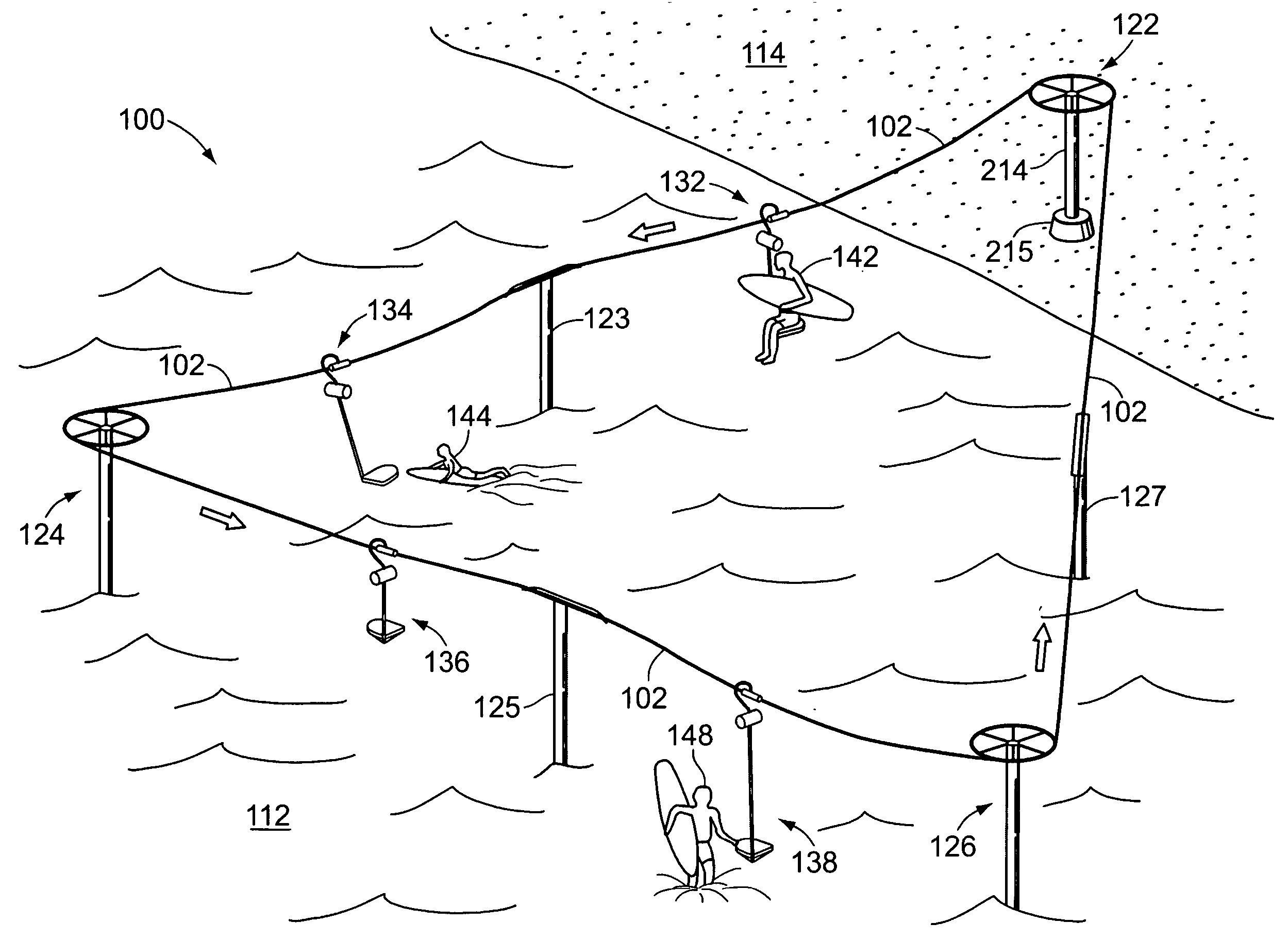
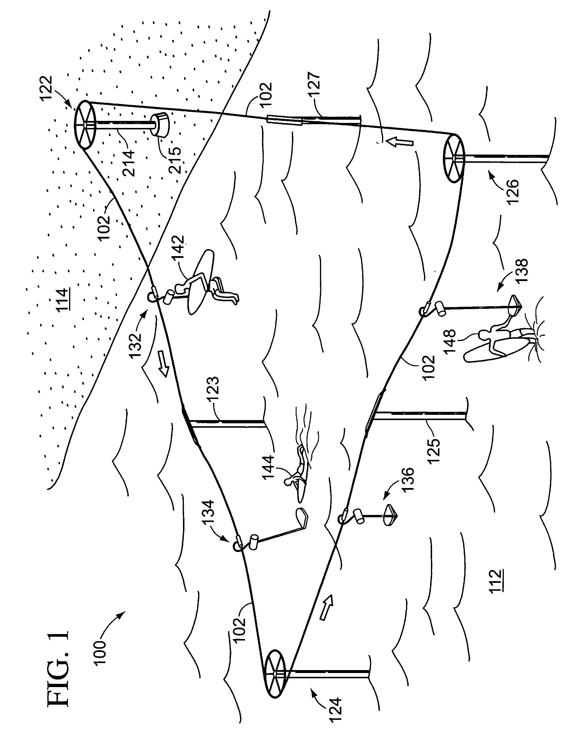
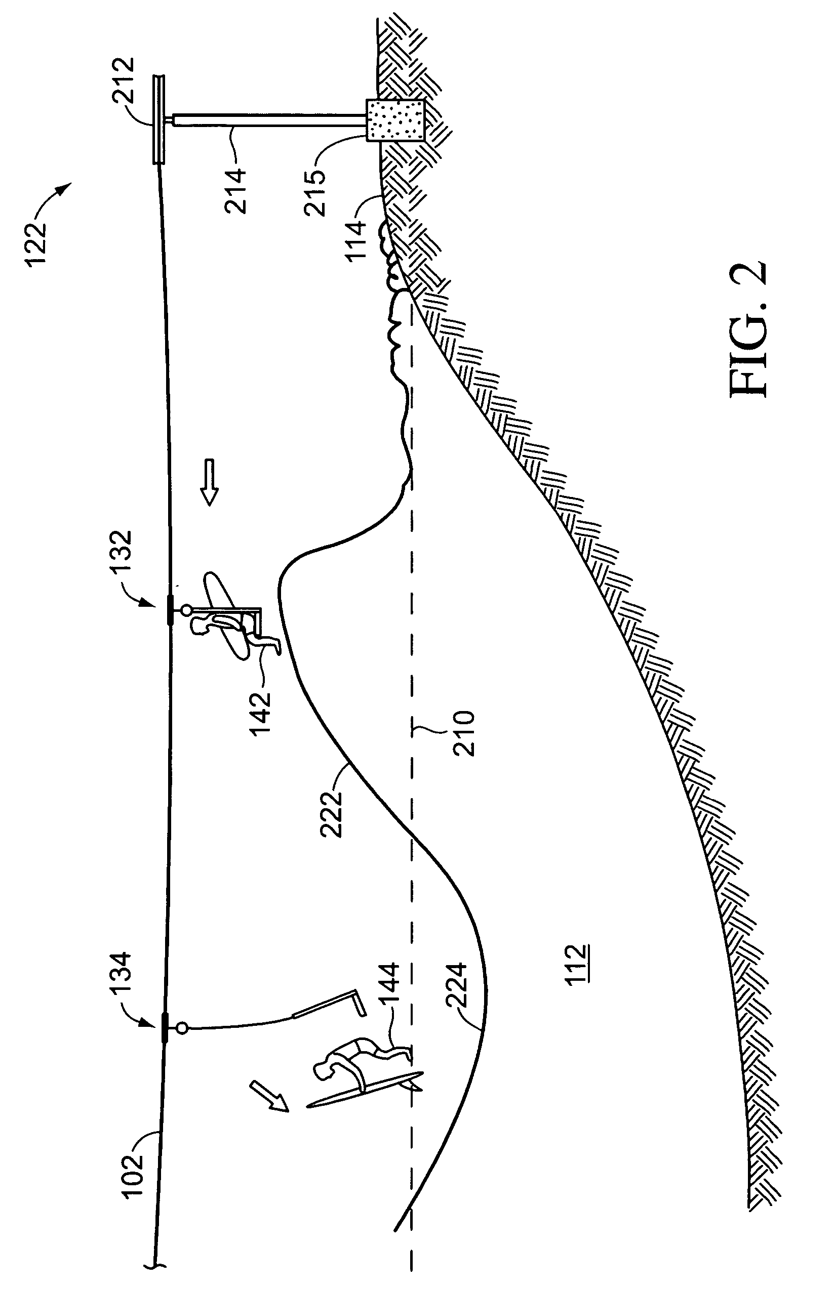
[0013] A surfer lift system according to various aspects of the present invention is illustrated in the figures. FIG. 1 illustrates an exemplary system 100 including a lift cable 102 that circulates in a continuous loop between opposing support pylons 122, 124, 126 and extends partially over a region of water 112 near a beach 114. Pylon 122 stands on beach 114 with its mast 214 anchored in a concrete block 215 deep enough and securely enough beneath the surface of beach 114 to counter tension in cable 102. Opposing pylons 124, 126 extend above water 112 from bases (not shown) similarly anchored in the seabed beneath water 112. Intermediate support pylons 123, 125, 127 limit sag and tension on lift cable 102 between pairs of opposing support pylons. Alternatively, pylon 122 can be placed just offshore or formed in conjunction with a pier or other shoreline structure.

[0014] Rider supports 132, 134, 138 connect to lift cable 102 and suspend riders 142, 144, 148 from cable 102. System ...


PUM


Abstract

A rider is suspended a distance beneath a lift cable and moved over a region of water with incoming waves. The distance that the rider is suspended beneath the lift cable is controllably increased and, thereafter, the rider enters the water, such as to surf the waves. The rider can control the increase in distance individually, lowering himself or herself at will after spotting a desirable place to enter the water, e.g., just after the crest of an incoming wave. The initial distance, i.e., the distance below the cable before the rider is lowered toward the water, can be set to carry the rider high enough to pass over the crests of the waves. Various other aspects, apparatus, and variations are also disclosed.

Description

CROSS-REFERENCE TO RELATED APPLICATIONS [0001] This application claims the benefit of U.S. provisional application Ser. No. 60 / 593,546, filed Jan. 24, 2005.BACKGROUND OF THE INVENTION [0002] In the sports of skiing and surfing, the rider must move against the natural forces of gravity or incoming wave action to reach a point where he or she can harness those natural forces to ride down a hillside or along the face of a wave. Few skiers would consider engaging in their sport without the benefit of powered lifts to overcome gravity and start their runs high up on the hillside. Despite the long-standing availability of several expired patents that teach offshore towing systems, most surfers still rely on paddling and rip currents to reach desirable offshore locations for riding incoming waves. [0003] For example, U.S. Pat. No. 3,181,861 to Wilkinson discusses a system for installation at beaches to allow riders to be carried on tow bars along the surface of the water to an offshore loc...

Claims


Application Information

Patent Timeline
IPC IPC(8): B63B35/79
CPCA63C19/00B61B11/00
Inventor KIAN, KIANOUSHFOROUDI, MAXANDERSON, SEAN
Owner MKS ENTERPRISES
Why Eureka
Try Eureka