

Golf club head
- Summary
- Abstract
- Description
- Claims
- Application Information
AI Technical Summary
Benefits of technology
Problems solved by technology
Method used
Image

Examples
first embodiment
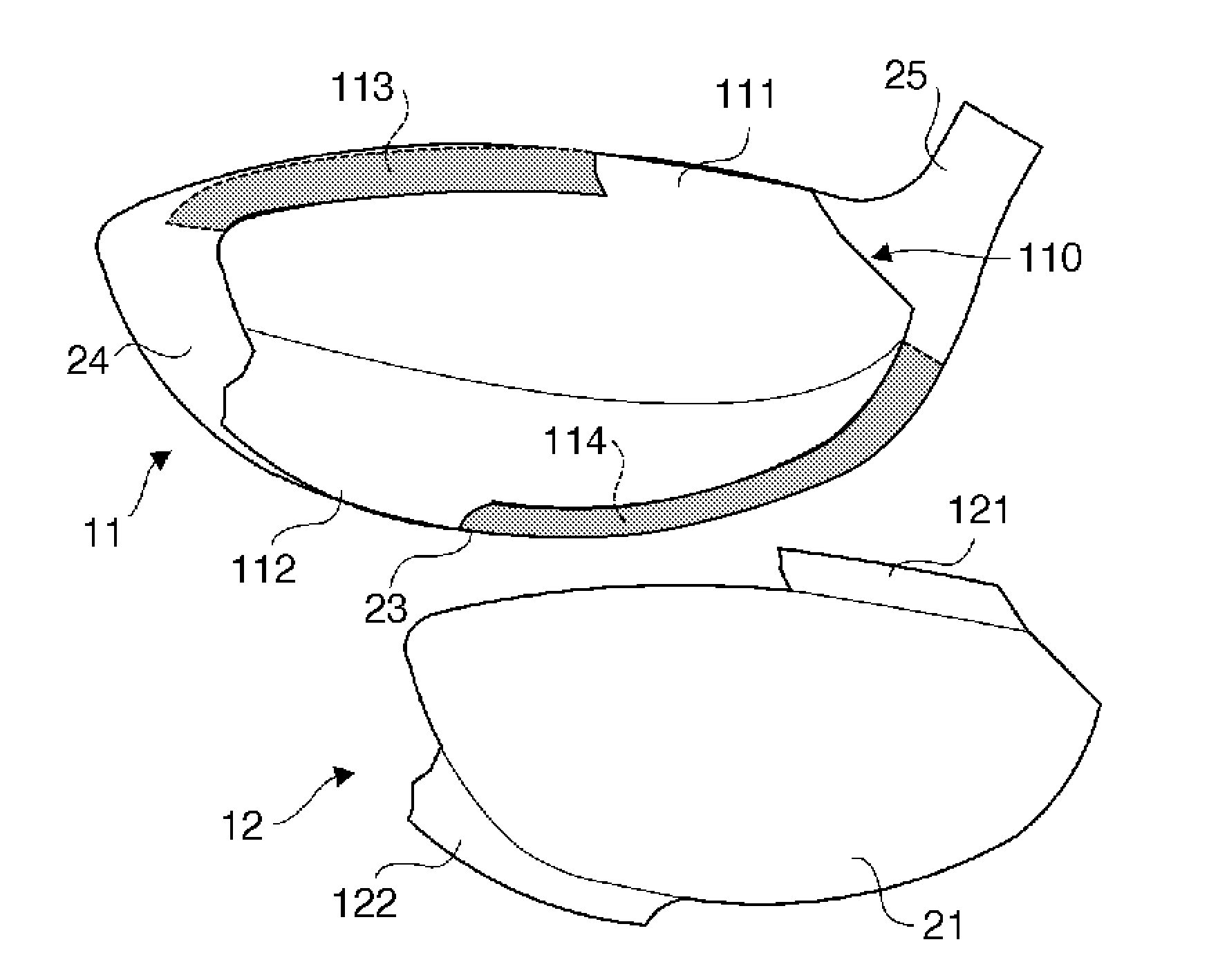
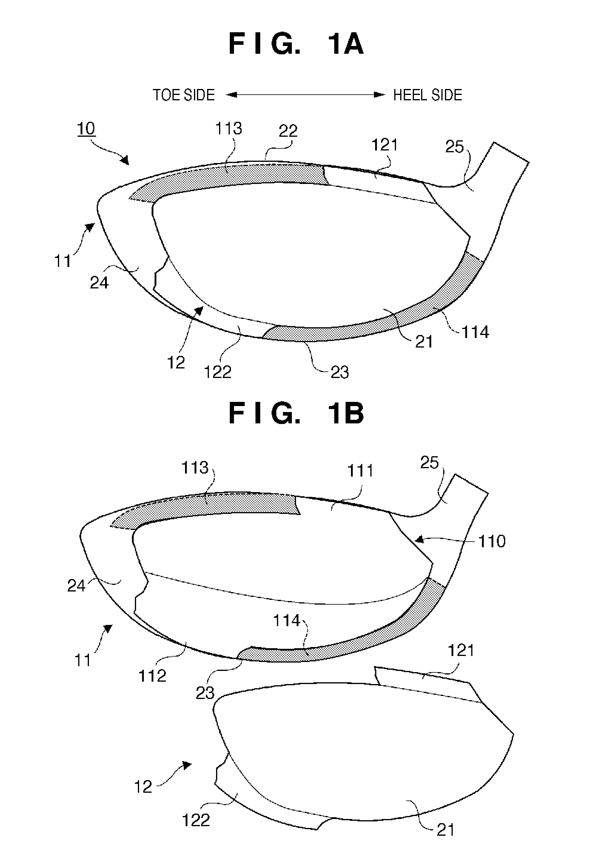
[0020]FIG. 1A is a front view (a view when viewed from the side of a face portion 21) of a golf club head 10 according to an embodiment of the present invention. FIG. 1B is an exploded view of the golf club head 10. The golf club head 10 is hollow, and its peripheral wall forms the face portion 21, a crown portion 22, a sole portion 23, and a side portion 24. The face portion 21 forms the face surface (striking surface). The crown portion 22 forms the upper portion of the golf club head 10. The sole portion 23 forms the bottom portion of the golf club head 10. The side portion 24 forms the side portion of the golf club head 10. The golf club head 10 also includes a cylindrical hosel portion 25 to which a shaft is attached.
[0021]The golf club head 10 is a driver golf club head. However, the present invention is applicable not only to driver golf club heads but also to wood type golf club heads including, for example, a fairway wood type golf club head, utility (hybrid) type golf club...
second embodiment
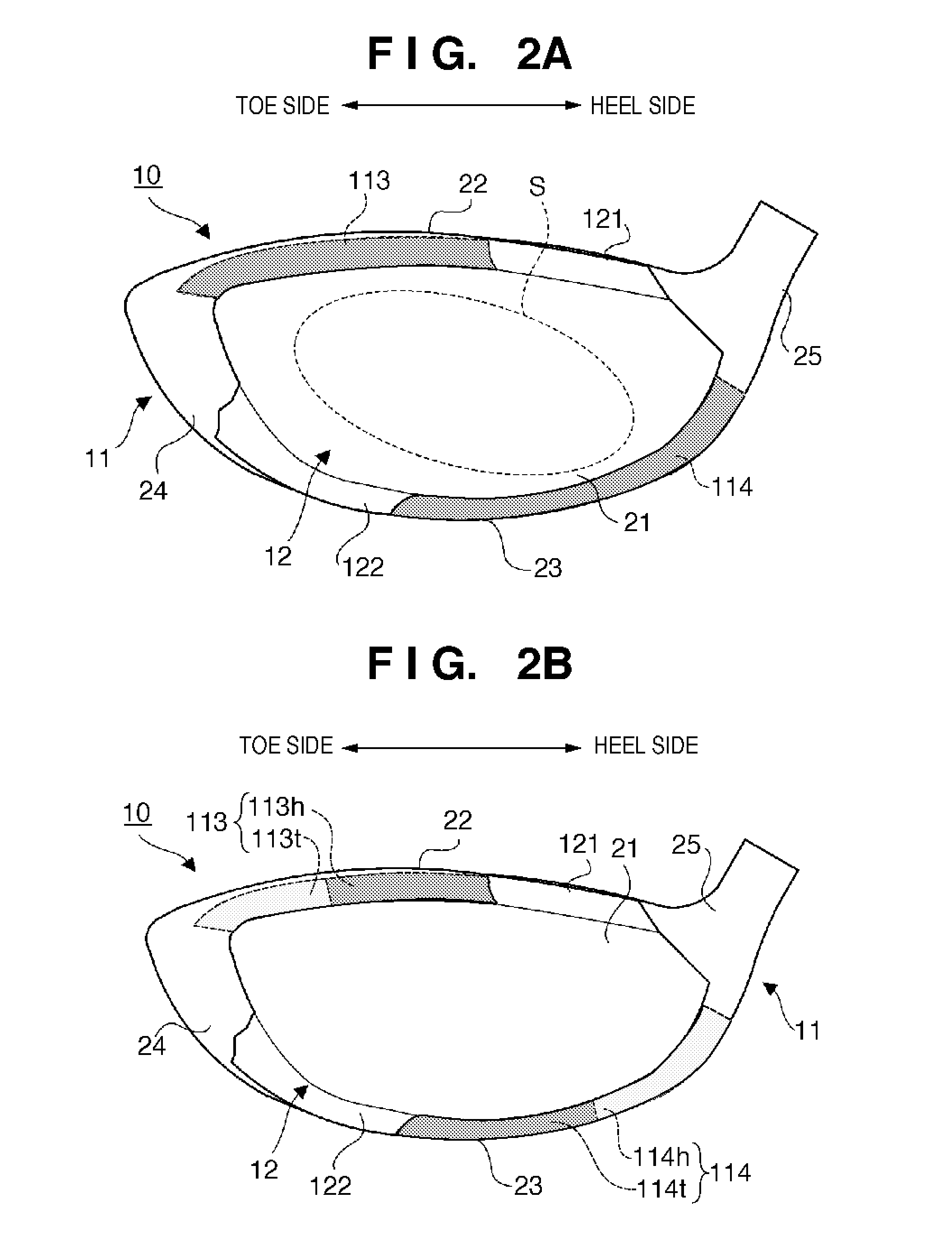
[0031]Although the rigidities of the portions 113 and 114 are uniform in the first embodiment, they may differ between the heel and toe sides. FIG. 2B is an explanatory front view of a golf club head 10 according to this embodiment. The same reference numerals as in the golf club head 10 according to the first embodiment denote the same constituent elements in the second embodiment, and a description thereof will not be given.
[0032]A heel-side region 113h of a portion 113 is more rigid than its toe-side region 113t. A heel-side region 114h of a portion 114 is more rigid than its toe-side region 114t. To make such differences in rigidity, the above-mentioned first to third methods can be adopted.
[0033]In this manner, the rigidity of the portion 113 is set relatively low on the toe side, and that of the portion 114 is set relatively low on the heel side, thereby making it easier for a region of a face portion 21, which is on the side of a crown portion 22 and on the toe side, and that...
third embodiment
[0035]The portion 113 may extend to the side portion 24. FIG. 3A is an explanatory front view of a golf club head 10 according to this embodiment. The same reference numerals as in the golf club head 10 according to the first embodiment denote the same constituent elements in the third embodiment, and a description thereof will not be given.
[0036]A portion 113′ which substitutes for the portion 113 extends to a side portion 24, and reaches a notch portion 112. Although the overall rigidity of the portion 113′ may be uniform, a heel-side region 113h of the portion 113′ is more rigid than a toe-side region 113t′ of the portion 113′ in this embodiment, as in the second embodiment. In this manner, the sweet area can be more reliably widened to a region of a face portion 21, which is on the side of a crown portion 22 and on the toe side, by extending the portion 113′ to the side portion 24. The sweet area can be still more reliably widened to the region of the face portion 21, which is o...
PUM
 Abstract
Description
Claims
Application Information