Method and apparatus for communicating with blind interference alignment using power allocation and/or transmission architecture

a transmission architecture and blind interference technology, applied in the field of multi-input multiple output (mimo) wireless transmission systems, can solve the problems of limiting the net spectral efficiency increase that can be obtained, knowing the channel state between transmitting and receiving antennas, and requiring system cos

Active Publication Date: 2012-03-08
NTT DOCOMO INC
View PDF4 Cites 24 Cited by
  • Summary
  • Abstract
  • Description
  • Claims
  • Application Information

AI Technical Summary

Benefits of technology

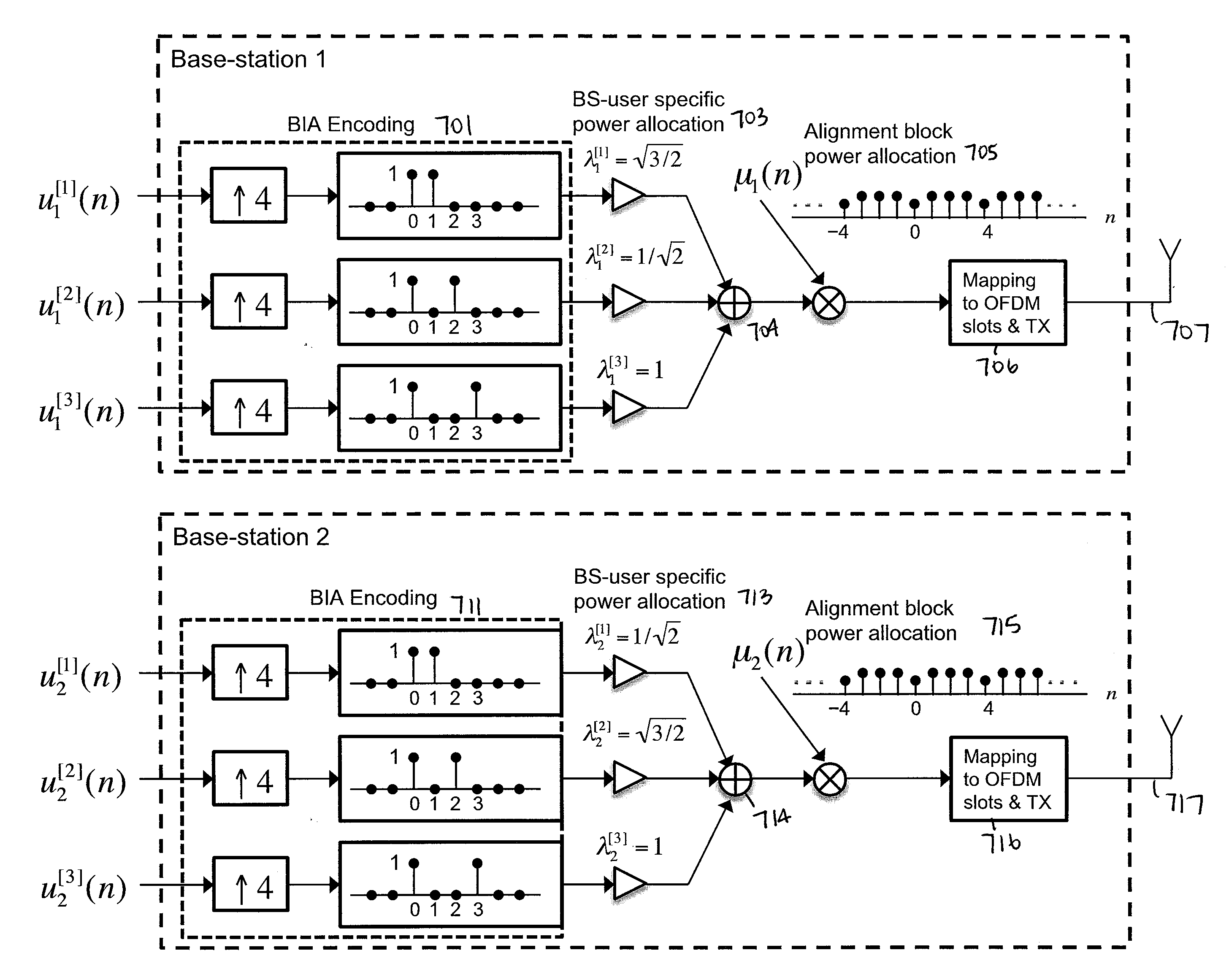
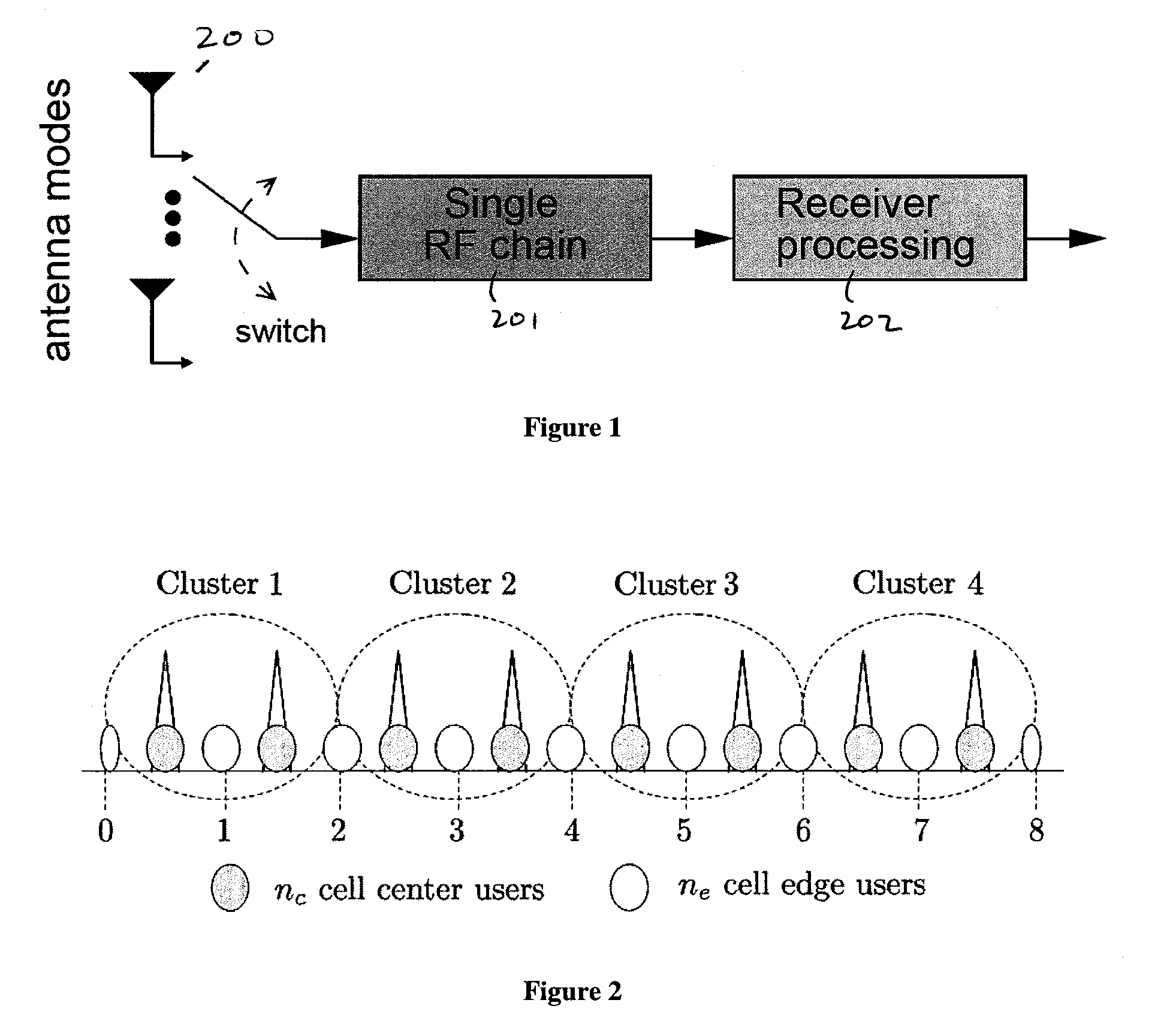
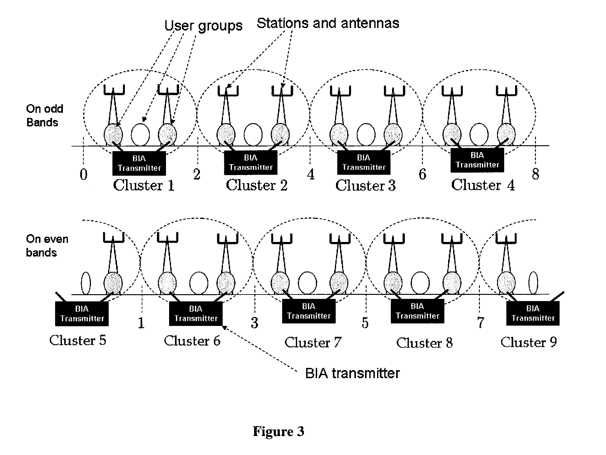
[0022]A method and system are disclosed herein for power allocation and / or clustering in a wireless communication system that uses blind interference alignment. In one embodiment, the system comprises a plurality of receivers, where each receiver in the plurality has a multi-mode antenna with a single radio frequency (RF) chain that is operable in a plurality of antenna modes, and wherein each receiver shifts between the plurality of antenna modes in a predetermined manner. The system also includes a plurality of base stations to perform cluster-based transmission, each base station in the plurality of base stations having one or more transmitters having a transmit antenna and being operable to communicate with one or more of receivers in the plurality of receivers using a blind interference alignment (BIA) scheme, and wherein the plurality of base stations are grouped in different clusters at different times according to cluster patterns.

Problems solved by technology

Exploiting such DoFs often requires some amount of cost to the system.
One such cost is knowledge of the channel state between transmitting and receiving antennas.
It is a fundamental issue often overlooked in assessing conventional MIMO.
Such CSI-related overhead in fact can represent a fundamental “dimensionality bottleneck” that can limit the net spectral efficiency increase that can be obtained with conventional CSI-dependent MIMO.
This overhead increase can limit continued growth in throughput if spectral efficiency improvements do not offset increased CSI overheads.
Clearly, such a system would not support unbounded increases in Nt.
BIA techniques do have some inherent challenges and limitations in the scenarios in which they can be used.
The first inherent problem is that they often require high Signal to Noise Ratios (SNRs) to operate effectively, e.g. the original BIA scheme may require up to 20 dB of SNR.
This is due to a property of the interference alignment process which results in noise being amplified in the resulting interference-aligned streams.
As a consequence of this, the original BIA technique has limited application to many users in a cellular environment.
Unfortunately, it is such lower SNR users that are often the ones that need techniques to help them boost their spectral efficiency.

Method used


Image

  • Method and apparatus for communicating with blind interference alignment using power allocation and/or transmission architecture
  • Method and apparatus for communicating with blind interference alignment using power allocation and/or transmission architecture
  • Method and apparatus for communicating with blind interference alignment using power allocation and/or transmission architecture

Examples


example 1

Original BIA scheme with M=2, K=2

[0062]Encoding and Transmission: This is the easiest and most illustrative case of the BIA process. In this case the alignment code has length L=3. It delivers to each user, user k=1 and user k=2, a single 2 dimensional symbol (or block of 2-dimensional symbols). That is, N=1.

[0063]Let s[k] denote the 2×1 coded symbol (or coded block) for users k, for k=1 and 2, and x(t) denote the transmitted signal (an M-dimensional quantity) at slot t. The code is as follows:

x=[x(1)x(2)x(3)]where[x(1)=s[1]+s[2]]←Blocktype-1[x(2)=s[1]x(3)=s[2]]←Blocktype-2(equation1)

[0064]Here a stream s[k] is a vector of two dimensions of the form

s[k]=[u1[k]u2[k]]

where u1[k] is ith the information bearing stream supporting data intended for user k.

[0065]Recall that each “symbol” can refer to a single numerical value, or can signify a block of such symbols. For simplicity in exposition, the word “symbol” refers herein to either case.

[0066]In order to facilitate interference alignme...


PUM


Abstract

A method and system are disclosed herein for power allocation and/or clustering in a wireless communication system that uses blind interference alignment. In one embodiment, the system comprises a plurality of receivers, where each receiver in the plurality has a multi-mode antenna with a single radio frequency (RF) chain that is operable in a plurality of antenna modes, and wherein each receiver shifts between the plurality of antenna modes in a predetermined manner. The system also includes a plurality of base stations to perform cluster-based transmission, each base station in the plurality of base stations having one or more transmitters having a transmit antenna and being operable to communicate with one or more of receivers in the plurality of receivers using a blind interference alignment (BIA) scheme, and wherein the plurality of base stations are grouped in different clusters at different times according to cluster patterns.

Description

PRIORITY[0001]The present patent application claims priority to and incorporates by reference the corresponding provisional patent application Ser. No. 61 / 379,668, titled, “A Method to Deploy Efficient Blind Interference Alignment Using a Combination of Power Allocation and Transmission Architecture,” filed on Sep. 2, 2010.FIELD OF THE INVENTION[0002]Embodiments of the present invention relate to the field of Multiple Input Multiple Output (MIMO) wireless transmission systems; more particularly, embodiments of the present invention relates to Blind Interference Alignment (BIA) techniques that can be used to support Multi-User MIMO (MU-MIMO) transmission.BACKGROUND OF THE INVENTION[0003]Many recent advances in wireless transmission have rested on the use of multiple antennas for transmission and reception. Multiple antennas, fundamentally, can provide an increase in the numbers of Degrees of Freedom (DoFs) that can be exploited by a wireless system for transmission. Here, DoFs can be...

Claims


Application Information

Patent Timeline
Patent Type & Authority Applications(United States)
IPC IPC(8): H04B15/00H04W52/04
CPCH04B7/024H04B7/0452H04W52/30H04B7/0871H04W52/243H04B7/0822
Inventor PAPADOPOULOS, HARALABOS C.RAMPRASHAD, SEAN A.WANG, CHENWEI
Owner NTT DOCOMO INC
Why Eureka
Try Eureka