Anesthesia system and method

a technology of anesthesia and trachea, applied in the field of anesthesia system and method, can solve the problems of pneumatic leakage, dislodge the endotracheal tube, and performance of the tracheal intubation

Inactive Publication Date: 2012-03-15
GENERAL ELECTRIC CO
View PDF8 Cites 15 Cited by
  • Summary
  • Abstract
  • Description
  • Claims
  • Application Information

AI Technical Summary

Problems solved by technology

One problem with conventional medical ventilator systems relates to the performance of the tracheal intubations.
More precisely, improper placement of an endotracheal during a trache

Method used


Image

  • Anesthesia system and method
  • Anesthesia system and method
  • Anesthesia system and method

Examples


Embodiment Construction

[0012]In the following detailed description, reference is made to the accompanying drawings that form a part hereof, and in which is shown by way of illustration specific embodiments that may be practiced. These embodiments are described in sufficient detail to enable those skilled in the art to practice the embodiments, and it is to be understood that other embodiments may be utilized and that logical, mechanical, electrical and other changes may be made without departing from the scope of the embodiments. The following detailed description is, therefore, not to be taken as limiting the scope of the invention.

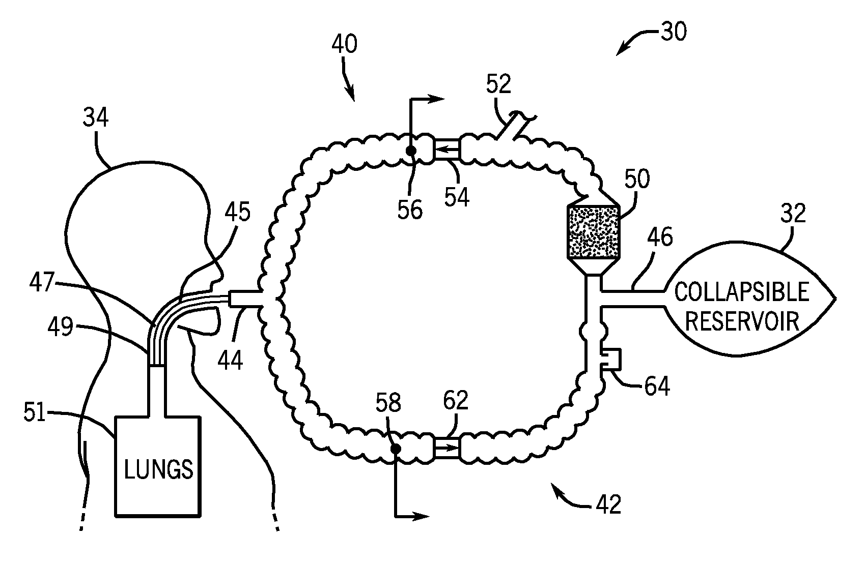
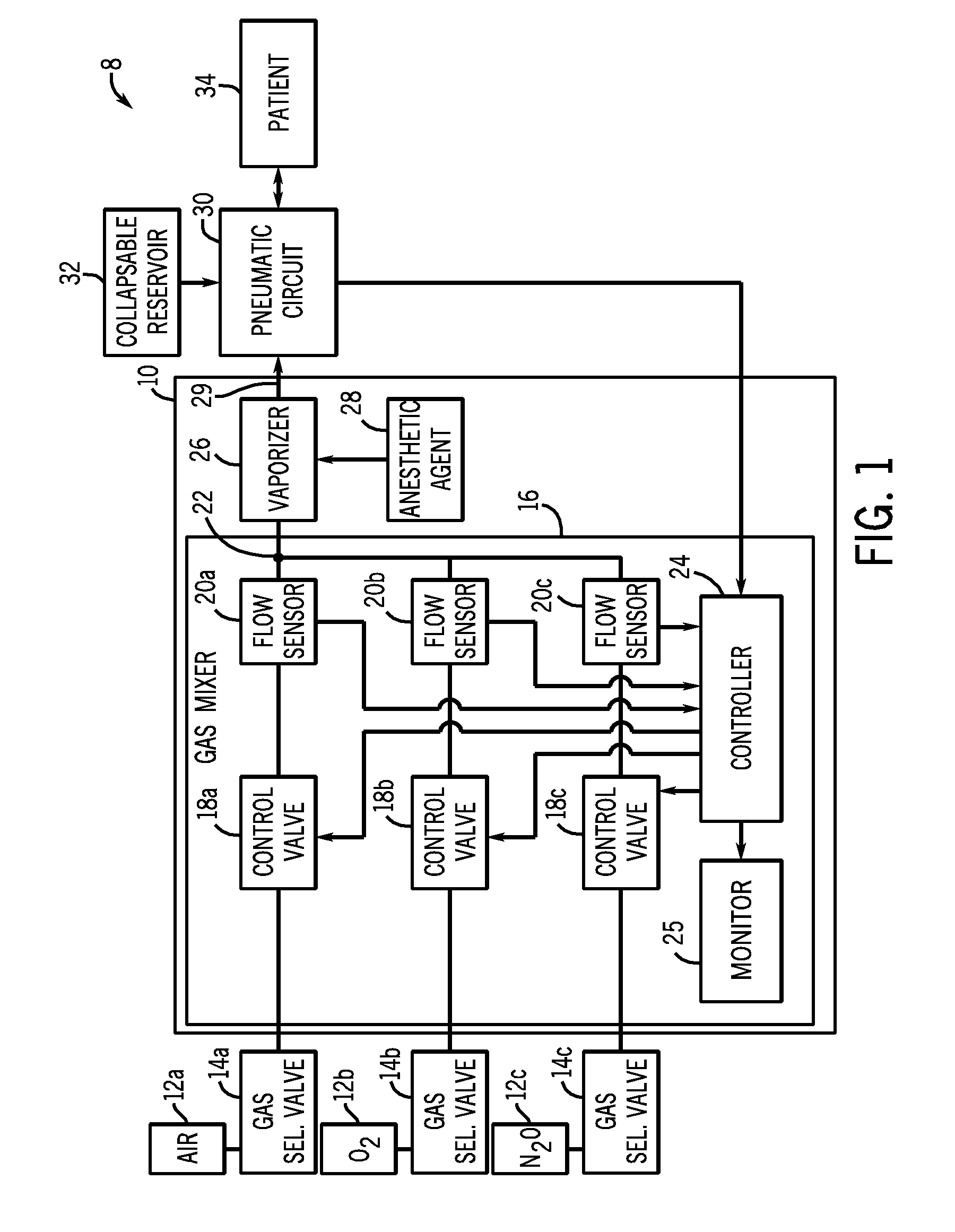
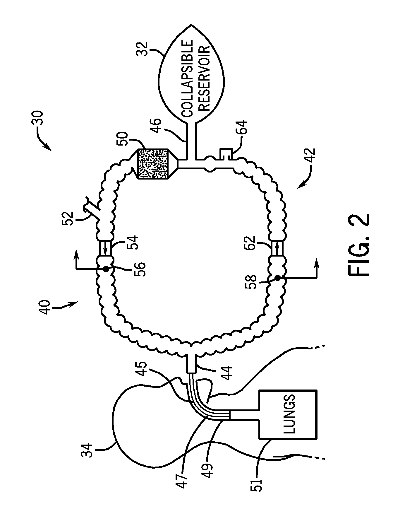
[0013]Referring to FIG. 1, an anesthesia system 8 is schematically depicted in accordance with an embodiment. The anesthesia system 8 includes an anesthesia machine 10, a plurality of gas storage devices 12a, 12b and 12c, a plurality of gas selector valves 14a, 14b, and 14c, a pneumatic circuit 30, and a collapsible reservoir or breathing bag 32. The anesthesia machine 10 is s...


PUM


Abstract

An anesthesia system is disclosed herein, The anesthesia system may include a pneumatic circuit comprising an inspiratory limb, an expiratory limb, and an endotracheal tube. The endotracheal tube may be configured to form a pneumatic coupling between a patient, the inspiratory limb and the expiratory limb. The anesthesia system may also include an anesthesia machine connected to the pneumatic circuit. The anesthesia machine may include a controller configured to identify the presence of a leak in the pneumatic coupling.

Description

FIELD OF THE INVENTION[0001]This disclosure relates generally to a system and method configured to automatically identify improper endotracheal tube placement.BACKGROUND OF THE INVENTION[0002]In general, medical ventilators systems are used to provide respiratory support to patients undergoing anesthesia and respiratory treatment whenever the patient's ability to breath is compromised. The primary function of the medical ventilator system is to maintain suitable pressure and flow of gases inspired and expired by the patient. Gases may be transferred to and from the patient via an endotracheal tube. The process of placing an endotracheal tube into a patient's trachea is called tracheal intubation.[0003]One problem with conventional medical ventilator systems relates to the performance of the tracheal intubations. More precisely, improper placement of an endotracheal during a tracheal intubation can produce a pneumatic leak. A pneumatic leak can dislodge the endotracheal tube, and int...

Claims


Application Information

Patent Timeline
IPC IPC(8): A61M16/01A61M16/04
CPCA61M16/0051A61M16/01A61M16/104A61M16/0891A61M16/22A61M2016/0036A61M2205/15A61M16/18A61M16/024
Inventor MASHAK, JAMES NYAL
Owner GENERAL ELECTRIC CO
Why Eureka
Try Eureka