

Brake booster system for a vehicle brake system and method for operating a vehicle brake system
- Summary
- Abstract
- Description
- Claims
- Application Information
AI Technical Summary
Benefits of technology
Problems solved by technology
Method used
Image

Examples
Embodiment Construction
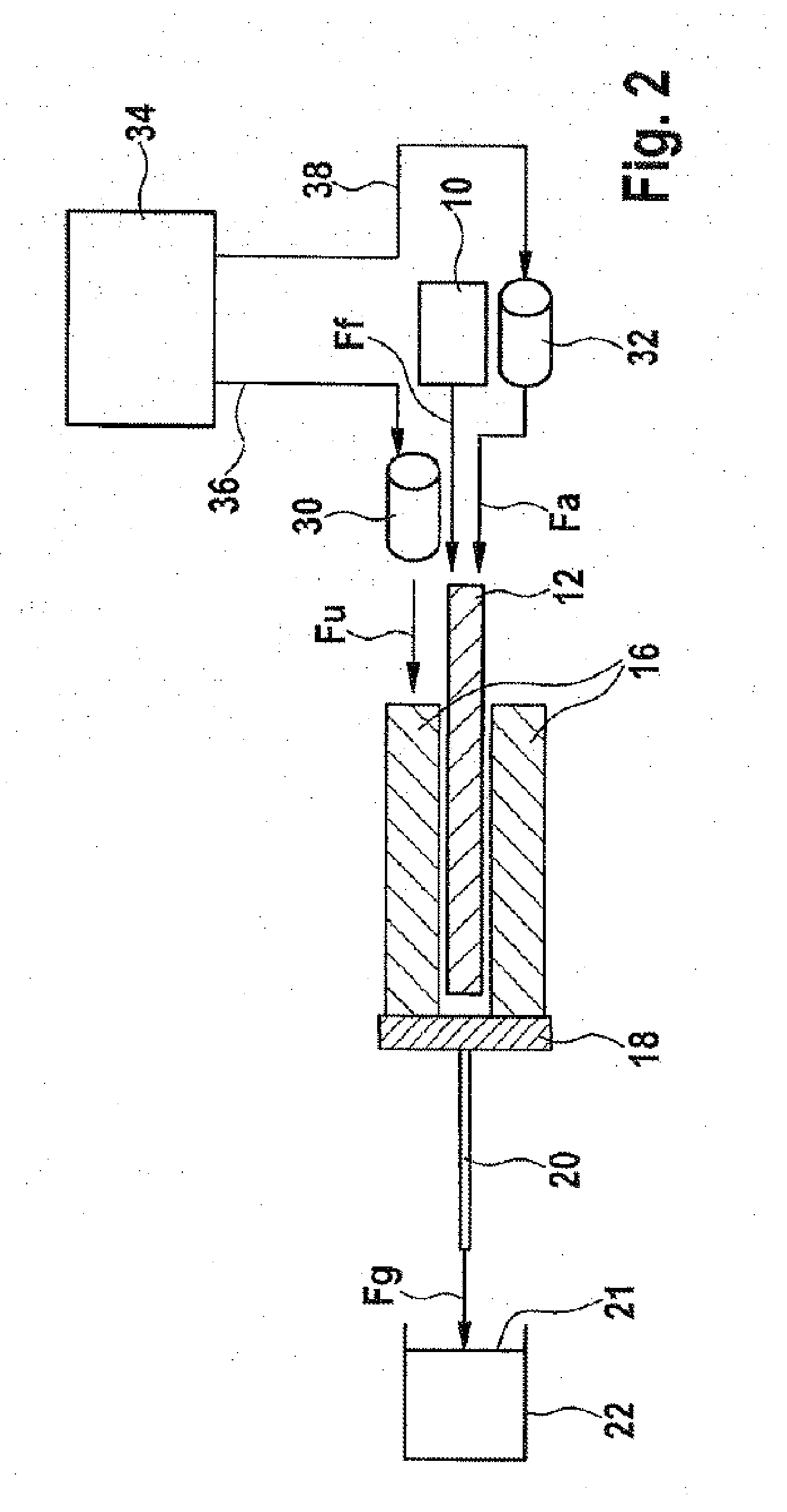
[0033]FIG. 2 shows a schematic diagram of one embodiment of the brake booster system.
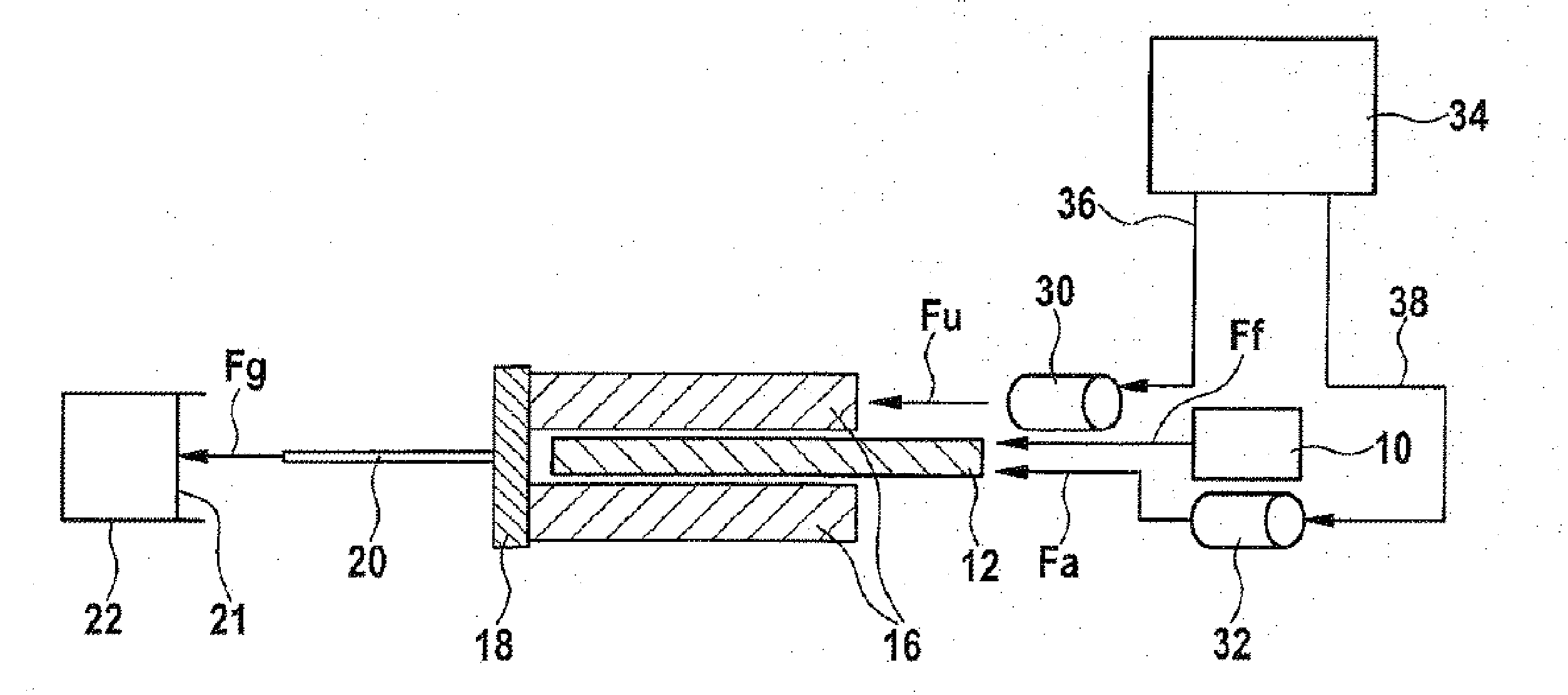
[0034]The brake booster system illustrated is arranged on a brake system having the components 10, 12 and 16 to 22 already described. The actuating element 10 of the brake system can be a brake pedal, for example. At least one brake circuit is connected to the force / pressure conversion element, which is designed as a brake master cylinder 22 and has the adjustable component 21.
[0035]The applicability of the brake booster system described below is not limited to a particular embodiment of a brake circuit filled with a brake gas or a brake fluid. For example, various alternative possibilities in terms of volume management in the brake system are conceivable. Since these are obvious for a person skilled in the art from the following descriptions, these are not explored in detail here.
[0036]Attention is drawn to the fact that the applicability of the brake booster system is also not limited to the coupl...
PUM
 Abstract
Description
Claims
Application Information