Lighting Apparatus And Lighting Fixture

Active Publication Date: 2011-04-28
PANASONIC CORP
View PDF4 Cites 6 Cited by
  • Summary
  • Abstract
  • Description
  • Claims
  • Application Information

AI Technical Summary

Benefits of technology

[0010]In view of the above insufficiency, the present invention has been aimed to propose a lighting apparatus an

Problems solved by technology

With respect to such the lighting fixture, when the light source comes close to the end of its life due to a long time use, a situation where the light source can not be turned on or the light source becomes hard to be turned on or the brightness of the light source is decreased occurs.
Long time use causes a situation, such as fatigue and/or oxidization of metal components of the lighting apparatus and/or the main body, deterioration, discoloration, and/or breakage of resin components thereof, and deterioration and/or decrease of dielectric resistance of circuit components of a lighting circuit.
Even if the lighting apparatus and the main body come close to the end of life, a user is unlikely to know that the lighting apparatus and the main body come to the end of life while the light source is normally turned on.
When the user continues to use the lighting apparatus and the main body which have already come to the end of life, it is impossible to obtain a proper performance of the lighting fixture.
In addition, breakage or fall of the main body

Method used


Image

  • Lighting Apparatus And Lighting Fixture
  • Lighting Apparatus And Lighting Fixture
  • Lighting Apparatus And Lighting Fixture

Examples


Example

First Embodiment

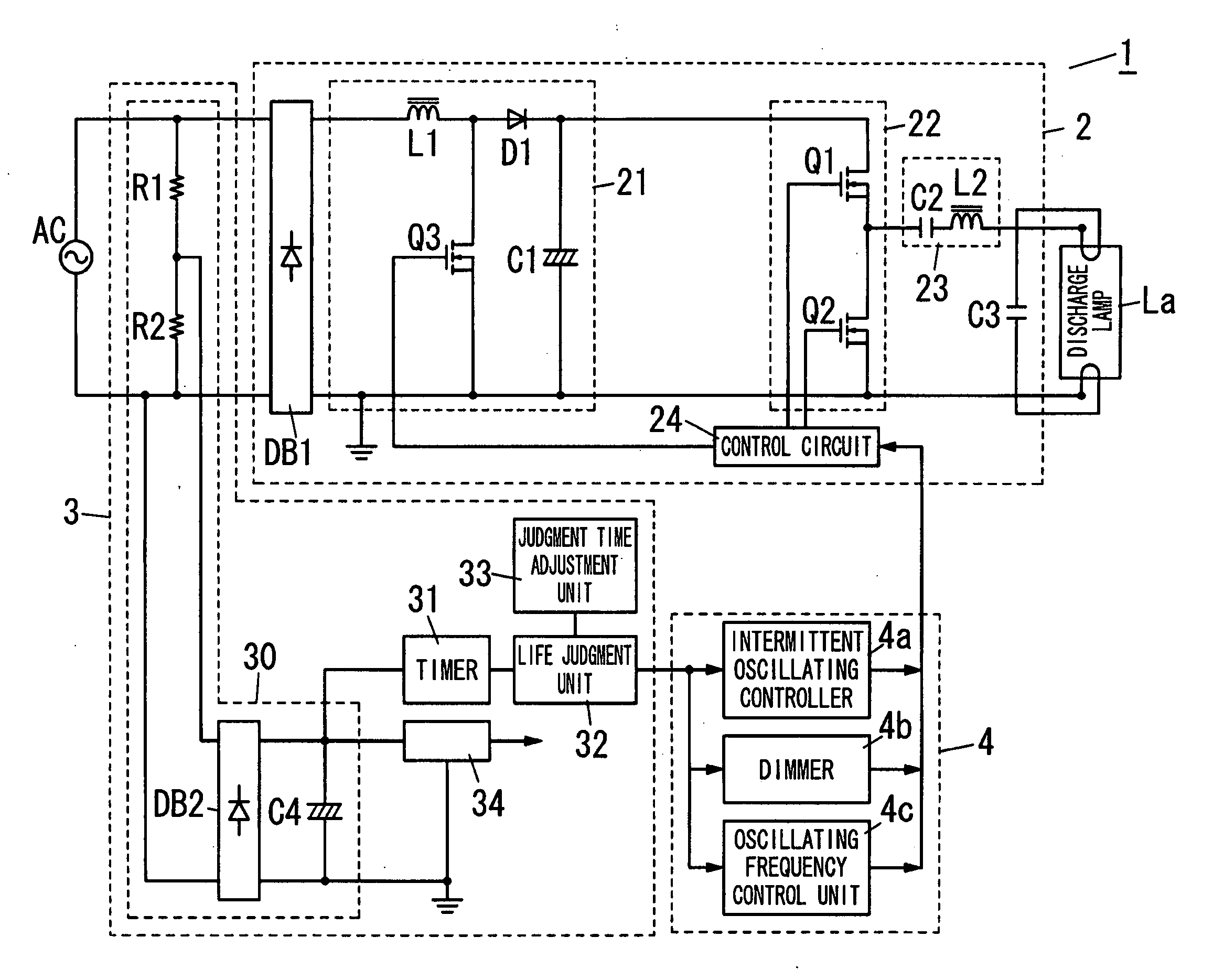
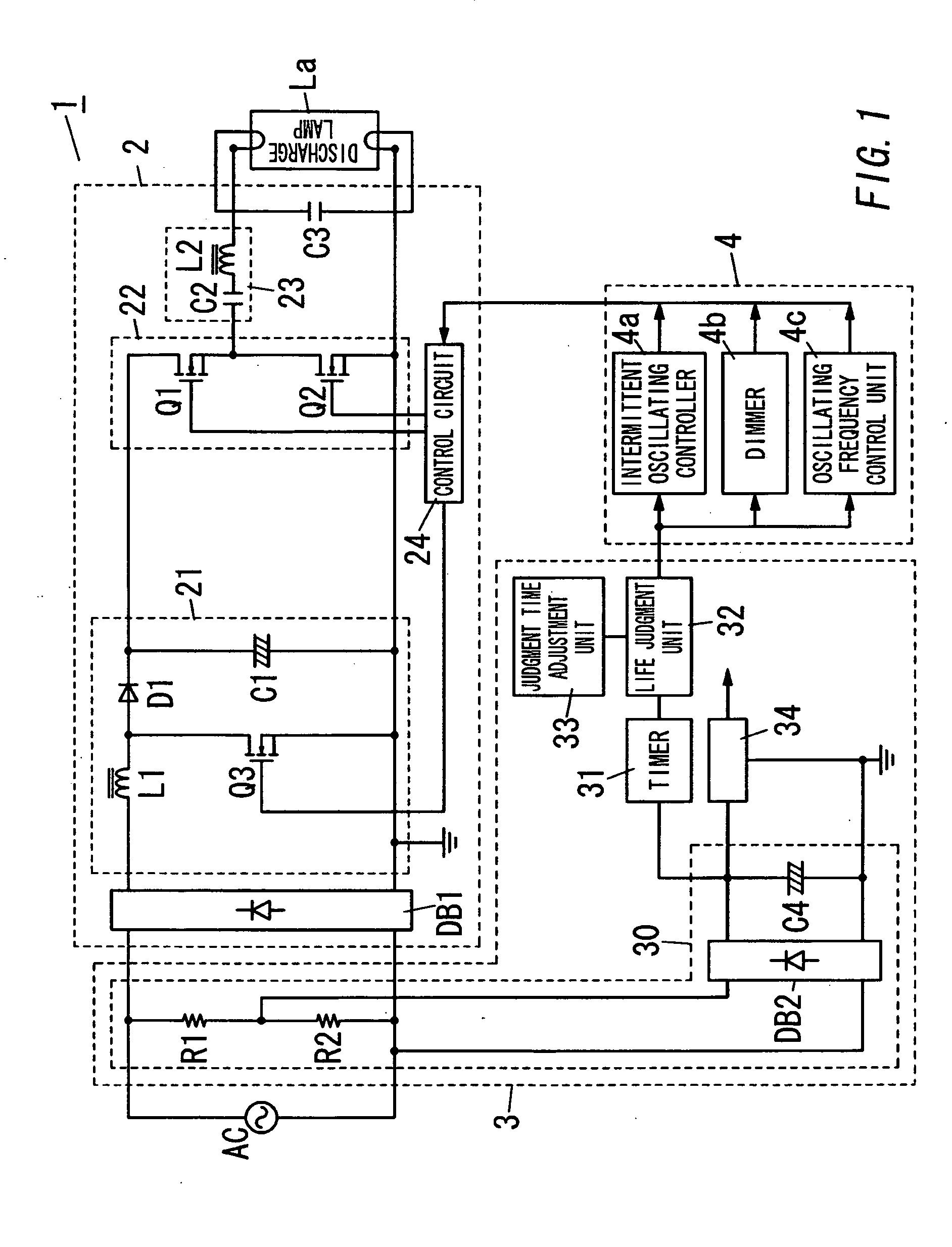
[0063]An explanation is made to the first embodiment of the present invention, with reference to FIGS. 1 and 2. FIG. 1 shows a circuit diagram of a lighting apparatus 1 of the present embodiment. This lighting apparatus 1 has primary components including a lighting circuit unit 2 configured to supply electrical power to a discharge lamp La, a life judgment block 3, and an indication unit 4. The lighting apparatus 1, the discharge lamp La turned on by the lighting apparatus 1, and a main body (not shown) configured to hold the lighting apparatus 1 and the discharge lamp La constitute a lighting fixture. With the exception of the life judgment block 3 and the indication unit 4, the lighting fixture has the same configuration and operation as a lighting fixture which is disclosed in Japanese patent laid-open publication No. 2006-236635. Therefore, no explanation is made to the same circuit configuration and operation.

[0064]The lighting circuit unit 2 includes a rectifie...

Example

Second Embodiment

[0092]The second embodiment of the present invention is explained with reference to FIGS. 3 and 4. FIG. 3 shows a circuit diagram of the lighting apparatus 1 of the present embodiment. The lighting apparatus 1 of the present embodiment is configured to turn on and off the electrodeless discharge lamp La. The electrodeless discharge lamp La has a transparent spherical glass bulb or a spherical glass bulb having its inner periphery coated by a fluorescent material which includes a discharge gas (e.g., combination gas of a mercury vapor and a noble gas) containing an inactive gas and a metal vapor. The lighting apparatus 1a includes the rectifier DB1, the chopper circuit 21, the inverter circuit 22, a starting circuit 26, a voltage detection circuit 27, and a control circuit 28. The lighting apparatus 1a further includes the life judgment block 3 and the indication unit 4 which are explained in the first embodiment. The rectifier DB1 is a diode bridge configured to mak...

Example

Third Embodiment

[0113]The third embodiment of the present invention is explained with reference to FIGS. 5 and 6. In the lighting apparatus 1 of the second embodiment, the accumulated operation time is measured by the timer 31 which measures the time in which the output voltage of the control source step-down circuit 30 decreasing the output voltage of the chopper circuit 21 is kept not less than the predetermined reference voltage. Meanwhile, in the present embodiment, as shown in FIG. 5, the timer 31 is configured to measure a time in which the detection voltage Vxs, which the voltage detection circuit 27 generates according to the output voltage of the inverter circuit 22, is kept not less than a prescribed reference voltage. With the exception of the measurement operation of the accumulated operation time by the timer 31, the lighting apparatus 1 of the present embodiment is the same as the lighting apparatus 1 of the second embodiment. Therefore, components common to the presen...


PUM


Abstract

A lighting apparatus includes a lighting circuit unit, a timer unit, a life judgment unit, a timing adjustment unit, and an indication unit. The lighting circuit unit is configured to activate a light source. The timer unit is configured to measure accumulated operation time of the lighting circuit unit. The life judgment unit is configured to store a first judgment time and a second judgment time longer than the first judgment time. The life judgment unit is configured to compare the accumulated operation time with the first judgment time and output a first judgment signal when the accumulated operation time becomes equal to the first judgment time. The life judgment unit is configured to compare the accumulated operation time with the second judgment time and output a second judgment signal when the accumulated operation time becomes equal to the second judgment time. The timing adjustment unit is configured to vary timing at which the life judgment unit outputs the first judgment signal. The timing adjustment unit is configured to vary timing at which the life judgment unit outputs the second judgment signal. The indication unit is configured to indicate, upon receiving the first judgment signal from the life judgment unit, a first level of the end of life with the light source kept turned on. The indication unit is configured to indicate, upon receiving the second judgment signal from the life judgment unit, a second level of the end of life. The second level of the end of life is later than the first level of the end of life.

Description

TECHNICAL FIELD[0001]The present invention is directed to a lighting apparatus and a lighting fixture.BACKGROUND ART[0002]In the past, a lighting fixture including a lighting apparatus configured to turn on a light source (e.g., a discharge lamp, an incandescent lamp, and an LED) has been proposed. With respect to such the lighting fixture, when the light source comes close to the end of its life due to a long time use, a situation where the light source can not be turned on or the light source becomes hard to be turned on or the brightness of the light source is decreased occurs. Therefore, a user can easily recognize the end of life of the light source in view of the above situation. Then, the user replaces the light source.[0003]Meanwhile, the lighting apparatus turning on the light source and a main body also have a useful life (that is, life). Long time use causes a situation, such as fatigue and / or oxidization of metal components of the lighting apparatus and / or the main body,...

Claims


Application Information

Patent Timeline
IPC IPC(8): H05B37/00
CPCH05B37/03H05B47/20H05B47/28
Inventor NAKAJO, AKIRAKIDO, HIROSHIURA, RYUSUKEKAKEHASHI, HIDENORIHIRAMATSU, KOHJIGOTO, KATSUYOSHI
Owner PANASONIC CORP
Why Eureka
Try Eureka