Interspinous process distraction device

a distraction device and process technology, applied in the field of interspinous process distraction devices, can solve the problems of inability to apply, too high cost of distraction devices, inferior applicability, etc., and achieve the effects of stable support of the spine, low cost, and high durability

Inactive Publication Date: 2012-03-15
KUO FAN CHING +2
View PDF16 Cites 20 Cited by
  • Summary
  • Abstract
  • Description
  • Claims
  • Application Information

AI Technical Summary

Benefits of technology

[0008]Accordingly, the primary object of the present invention is to provide an interspinous process distraction device which can stably support a spine, and is provided with a low cost as well as high durability.
[0013]The adjustable interspinous process distraction device of the present invention is at least provided with following advantages and functional improvements:
[0014]1. Compared to the prior art where many vertebrae are tied and positioned together, the present invention only positions two adjacent spinous processes at a time; therefore, a movement between the vertebrae, excessive stiffness of the spine or a pain which can be easily formed at the spine by a slight movement can be avoided, thereby providing better comfortableness.
[0015]2. Compared to the existing interspinous process distraction device, the present invention eliminates the structures of screw hole and stud; therefore, the high cost due to that the structures are too complicated can be avoided. In addition, tooth collapse to the screw hole under many times of adjustment can be prevented.
[0016]3. The present invention can provide the stable support to two adjacent vertebrae, thereby achieving an object of intensifying the skeleton structure.

Problems solved by technology

As a person gets older, the spine is aged or an accidental injury occurs, the vertebra can be injured that spacing between two adjacent vertebrae is shortened to compress the nerves, which harms the nerves and induces numbness as well as a feel of pain.
However, for the aforementioned distraction device which uses the stud and the screw hole, the structures are too complicated and an upper and lower vertebra of a patient can be easily lack of an elastic movement after using the stud, which results in a too high cost of the distraction device.
In addition, there is also an issue of inferior applicability.

Method used


Image

  • Interspinous process distraction device
  • Interspinous process distraction device
  • Interspinous process distraction device

Examples


Embodiment Construction

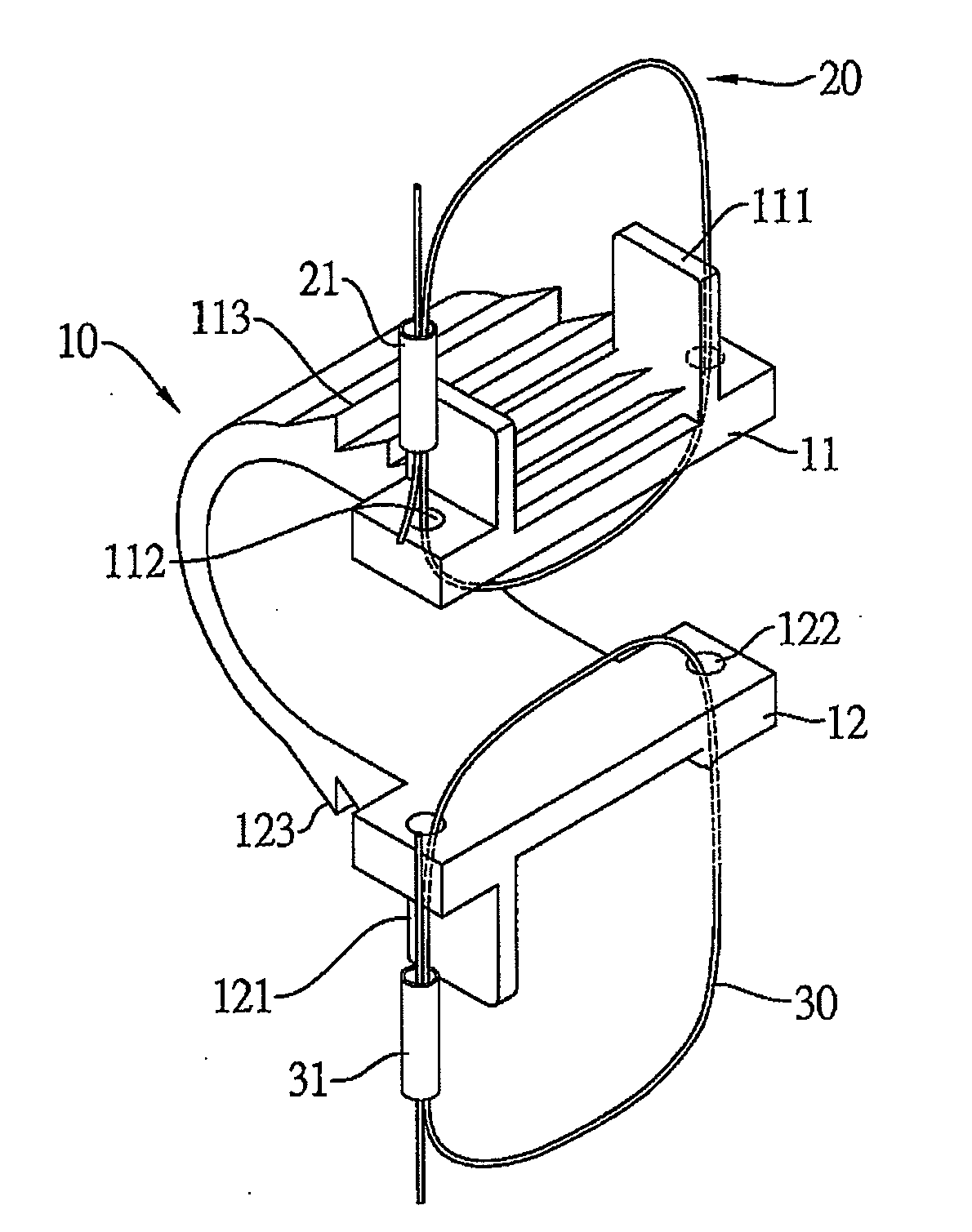
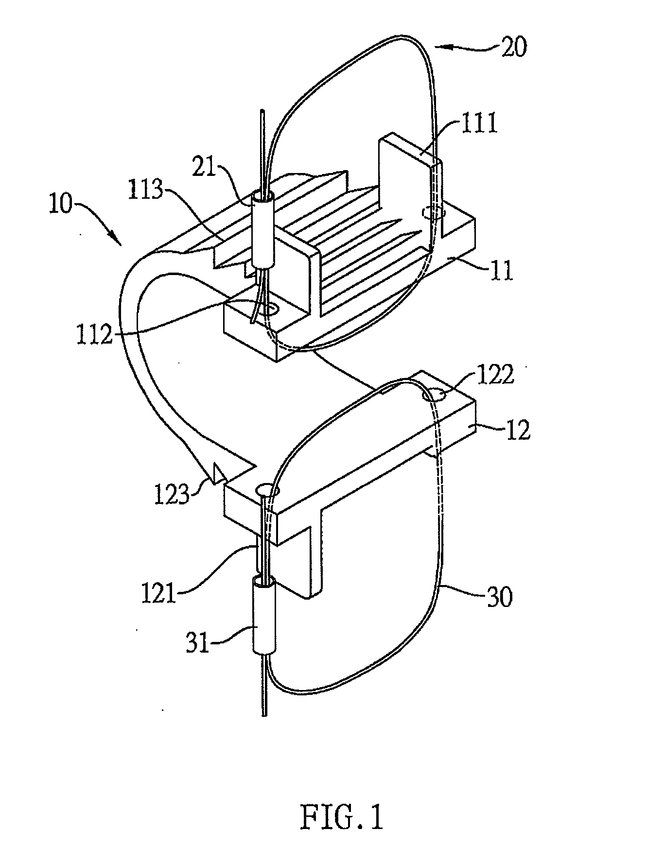
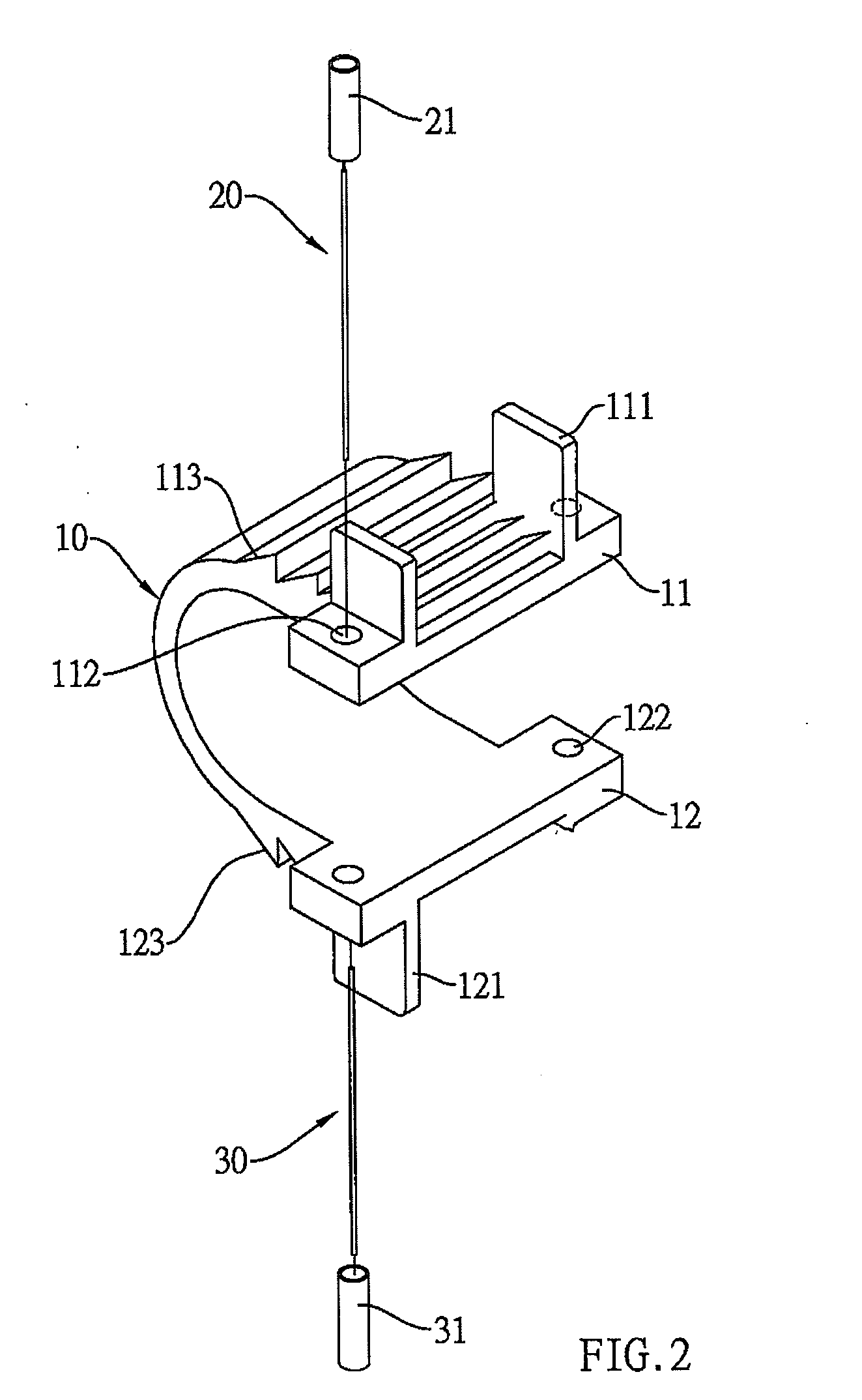
[0022]Referring to FIGS. 1 to 4, an adjustable interspinous process distraction device, according to the present invention, comprises a curved plate 10, an upper fixing wire 20 and a lower fixing wire 30.

[0023]The curved plate 10 is formed with an upper plate 11 and an opposite lower plate 12 by bending a board material (such as a thin metallic material). The upper plate 11 is penetrated with two upper wire holes 112, and the lower plate 12 is penetrated with two lower wire holes 122.

[0024]End parts and opposite exterior sides of the upper and lower plates 11, 12 are separated and longitudinally protruded with two upper clamp pieces 111 and a lower clamp piece 121, respectively. On the other hand, the opposite exterior sides of the upper and lower plates 11, 12 can be formed with inverted hooks 113, 123, with teeth of the inverted hooks 113, 123 facing toward the end parts of the upper and lower plates 11, 12.

[0025]The upper fixing wire 20 can be a metallic wire and its two ends pen...


PUM


Abstract

An interspinous process distraction device includes a curved plate which is formed with an upper plate and an opposite lower plate by bending a board material, with the upper plate being penetrated with two upper wire holes and the lower plate being penetrated with two lower wire holes; an upper fixing wire, two ends of which penetrate from bottom to top the two upper wire holes of the upper plate to be tied on a spinous process; and a lower fixing wire, two ends of which penetrate from top to bottom the two lower wire holes of the lower plate to be tied on the spinous process. This interspinous process distraction device is provided with a low manufacturing cost and high durability.

Description

BACKGROUND OF THE INVENTION[0001]a) Field of the Invention[0002]The present invention relates to an interspinous process distraction device, and more particularly to an interspinous process distraction device which can stably support a spine and is provided with a low manufacturing cost as well as high durability.[0003]b) Description of the Prior Art[0004]A spine is an essential part of a human skeleton, serving as a backbone of the skeleton to support muscles and organs in an upper half of the human body and linking with a lower half.[0005]The spine is formed by many vertebrae and an interior of each vertebra is passed through by many critical nerves. As a person gets older, the spine is aged or an accidental injury occurs, the vertebra can be injured that spacing between two adjacent vertebrae is shortened to compress the nerves, which harms the nerves and induces numbness as well as a feel of pain.[0006]An existing conventional structure includes an adjustable interspinous proces...

Claims


Application Information

Patent Timeline
Patent Type & Authority Applications(United States)
IPC IPC(8): A61B17/70
CPCA61B17/7062A61B17/7053
Inventor KUO, FAN-CHINGYANG, SHU-HUIKUO, YI-CHEN
Owner KUO FAN CHING
Why Eureka
Try Eureka