
Pressure-ulcer-prevention Dynamic Cushion

a cushion and pressure ulcer technology, applied in the field of human body support cushions, can solve the problems of not being able to pass air, the area surrounding the user's private part, and the buttocks of the cushion user's private part easily cumbersome with moisture, and causing tetter or itchy, and affecting the comfort of users

Inactive Publication Date: 2012-03-22
CHEN JOHN YANHAO
View PDF6 Cites 4 Cited by
  • Summary
  • Abstract
  • Description
  • Claims
  • Application Information

AI Technical Summary

Benefits of technology

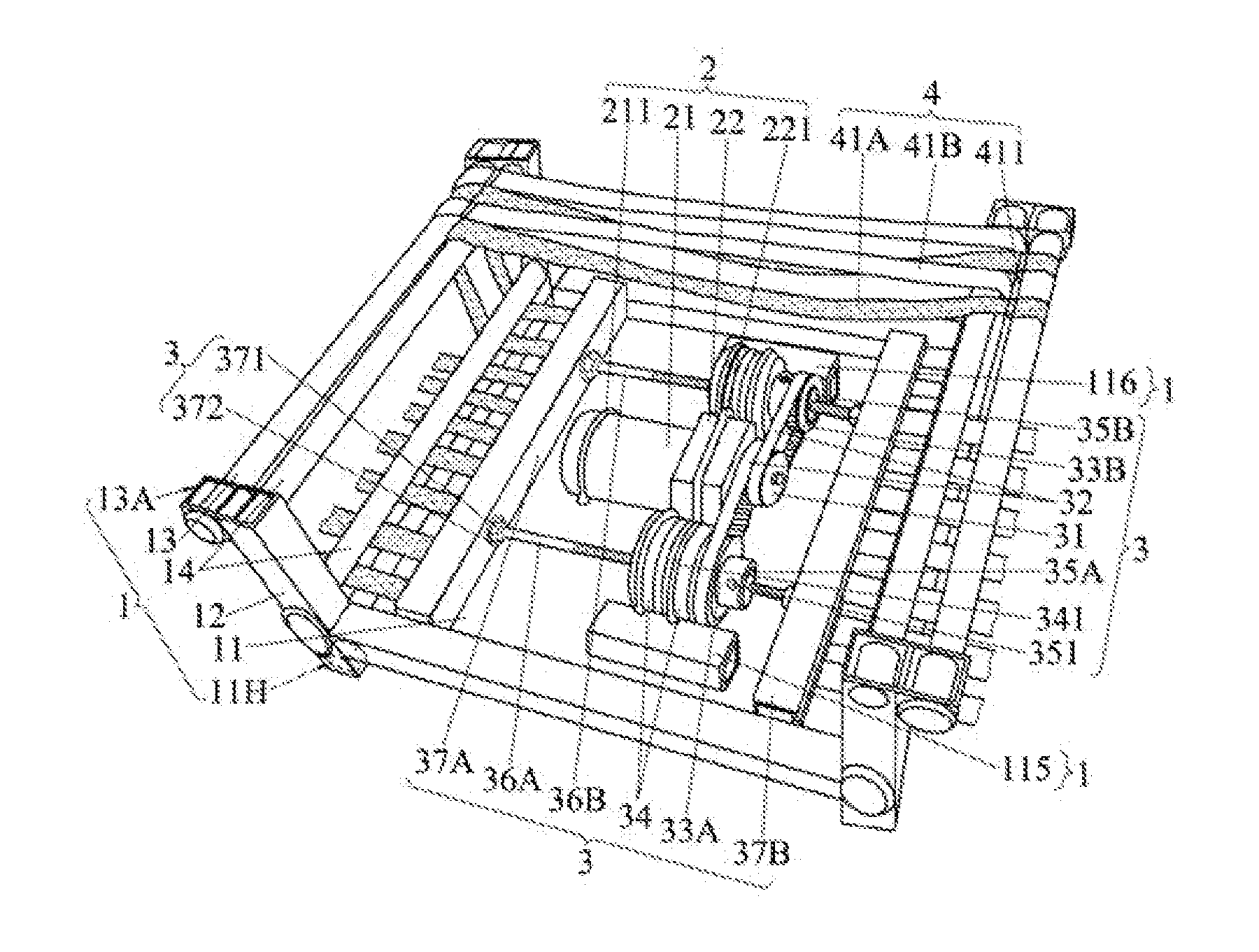
[0007]The invention provides a dynamic cushion which comprises: (a) a frame, (b) at least a driving source, (c) at least a transmission assembly, mechanically linked to the driving source(s) at one end, and firmly connected to plural horizontal, longitudinally-running strip-tail connectors in the frame at the other end, and (d) at least two, representing multiple-phase, interleaved-in-parallel strip clusters, including at least one strip cluster representing the odd phase and at least one strip cluster representing the even phase. The odd-phase strip cluster's head is (clusters' heads are) first fastened to the frame's one transverse side; the odd-phase strip cluster is (clusters are) then transversely wrapped across the frame's top surface and around the frame's other opposite transverse side so as to, respectively, fasten the strip cluster's tail (clusters' tails) to corresponding odd-phase strip-tail connector (connectors). Similarly, the even-phase strip cluster's head is (clusters' heads are) fastened to the frame's other transverse side; the even-phase strip cluster is (clusters are) then transversely wrapped across the frame's top surface and around the frame's one transverse side so as to, respectively, fasten the strip cluster's tail (clusters' tails) to corresponding even-phase strip-tail connector (connectors) in order to make the multiple-phase strip clusters produce, in turn, periodical, tension-and-relaxation-alternating, multiple-phase variations to avert any health hazards such as pressure ulcers.
[0008]The invention, from other embodiment with a two-phase structure, also provides a dynamic cushion that comprises: (a) a frame; (b) a driving source, having two output shafts; (c) a transmission assembly, having an inner end pair mechanically linked to the driving source, and an outer end pair in the opposite transverse sides respectively connected to two horizontal strip-tail connectors in the frame. The two strip-tail connectors are driven periodically by the driving source, in synchronism, moving periodically to and fro horizontally; and (d) two interleaved-in-parallel strip clusters, respectively representing two phases, with the first-phase strip cluster's head being fastened to the frame's one transverse side. The first-phase strip cluster is transversely wrapped across the frame's top surface and around the frame's other transverse side so as to fasten the strip cluster's tail to the first-phase strip-tail connector. The second-phase strip cluster's head is fastened to the frame's the other transverse side; the second-phase strip cluster is transversely wrapped across the frame's top surface and around the frame's one transverse side so as to fasten the strip cluster's tail to the second-phase's strip-tail connector in order to make the two strip clusters produce periodical, tension-and-relaxation-alternating, two-phase synchronized variations to avert any health hazards such as pressure ulcers.
[0009]The invention, from yet another embodiment with a three-phase structure, also provides a dynamic cushion that comprises: (a) a frame; (b) three driving sources; (c) three transmission assemblies, with their one end being respectively and mechanically linked to the three driving sources, and the other end being respectively connected to three horizontal, strip-tail connectors. The odd-phase and the even-phase strip-tail connectors are divided into, and located at, the two opposite transverse sides in the frame, in order to make the three strip-tail connectors, being respectively driven by the three driving sources in sequence, move periodically to and fro in sequence horizontally; and (d) one first-phase strip cluster, one second-phase strip cluster and one third-phase strip cluster, being interleaved in sequence and in parallel to constitute the frame's top surface, with the first and the third phases' strip-cluster heads being fastened to the frame's one transverse side, and the first and the third phases' strip clusters being transversely wrapped across the frame's top surface and around the frame's other transverse side so as to fasten the first phase and the third phase strip clusters' tails to the odd-phase strip-tail connectors. The second-phase strip cluster's head is fastened to the frame's the other transverse side; the second phase's strip cluster is transversely wrapped across the frame's top surface and around the frame's one transverse side so as to fasten the second phase strip cluster's tail to the even-phase strip-tail connector in order to make the three strip clusters produce periodical, tension-and-relaxation-alternating, three-phase variations to avert any health hazards such as pressure ulcers.

Problems solved by technology

The surfaces of the cushions available in the current market, including all makes of materials such as animal skin, rubber, bamboo, straw, wood, palm fiber, tea leaf, rice husk, and so on, and artificial materials, such as cloth, plastic sheet, artificial fibers, foams, gel, water bags, air bags, springs, and so forth, are mostly not air-passable, which causes the cushion user's buttocks and the area surrounding the user's private part easy to cumulate moisture and get moist tetter or itchy.
The capillary and minute vessels in that area, being pressed for too long, will gradually clog up, leading the area into ischemia and making the area's skin feel burning and uneasy.
The pressure-relieving and pressure-ulcer-prevention effects of such traditional cushions are far from ideal.

Method used


Image

  • Pressure-ulcer-prevention Dynamic Cushion
  • Pressure-ulcer-prevention Dynamic Cushion
  • Pressure-ulcer-prevention Dynamic Cushion

Examples


Embodiment Construction

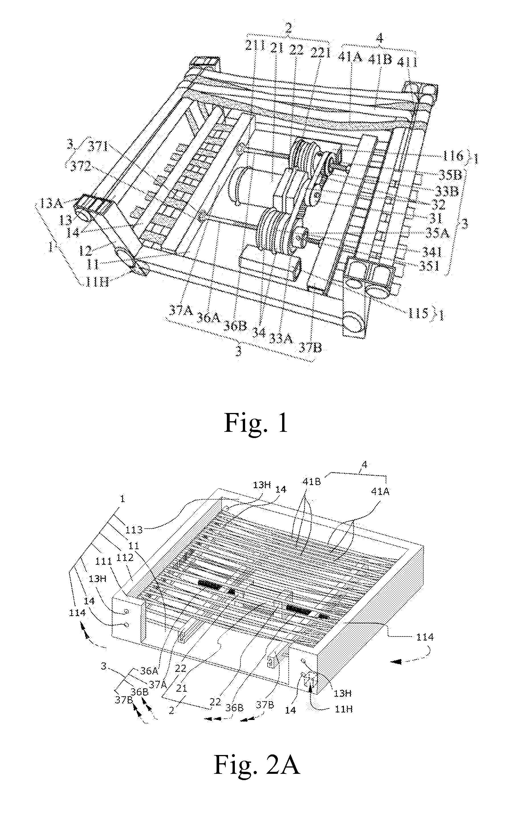
[0019]The invention includes four subsystems: (1) a frame, (2) at least a driving source, (3) at least a transmission assembly, and (4) plural, interleaved-in-parallel strip clusters divided into multiple phases. Hereinafter, the left-most digit of each part / component numeral shall numerically correspond to one of the above-listed subsystems; viz., 1 stands for frame 1, 2 driving source(s), 3 transmission assembly (assemblies), and 4 all plural strip clusters.

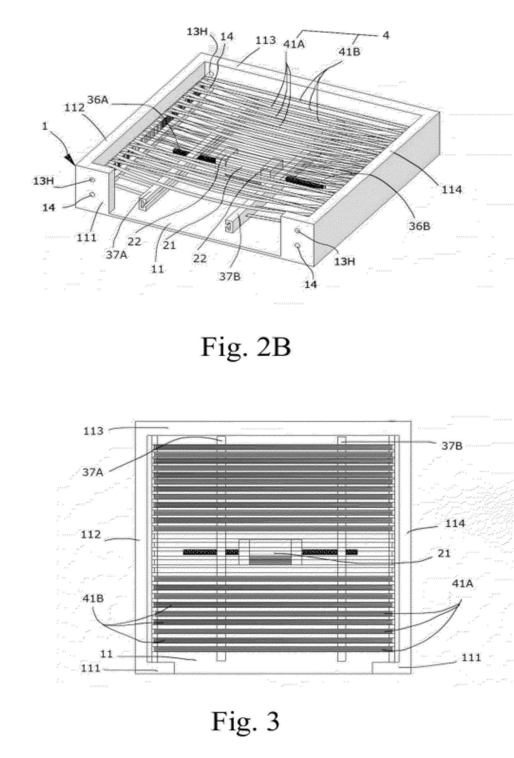
[0020]Two example molds, Mold 1 and Mold 2, for the invention's two-phase embodiments are used to explain and specify the present invention. The Mold 1 of the two-phase embodiments is shown in FIG. 1. The Mold 2 of same is shown in FIGS. 2A, 2B, 3, and 4, where FIG. 2A indicates a tightened first strip cluster and a loosened second strip cluster, FIG. 2B a tightened second strip cluster and a loosened first strip cluster, FIG. 3 the top view of FIG. 2A, and FIG. 4 the front view of FIG. 2A.

[0021]The definition of directions ado...


PUM


Abstract

This invented multiple-phase dynamic cushion comprises a frame, at least a driving source, at least a transmission assembly, and clusters of plural strips interleaved in parallel. Taking a two-phase embodiment as an example, the two-phase strips interleave with each other, in parallel, to form the cushion's surface and alternate their tensions in turn; when one phase's strips periodically tighten to support the user's body, the other phase's strips will loosen, allowing the user's body covered by the loosened strips to take a rest, averting a pressure-ulcer risk. The driving source is energized by an altering energy, making the two strip groups alternate in loosening and tightening states periodically in turn. This invention can be converted into a portable dynamic chair when the four holes on the bottom of its four corners are inserted with legs; it can also be converted into a dynamic support for a lying human body.

Description

CLAIM OF PROPERTY[0001]This application claims the benefit of Taiwan Patent Application No. 099131535, filed Sep. 17, 2010, the complete contents of which is hereby incorporated herein by reference.BACKGROUND OF THE INVENTION[0002]1. Field of the Invention[0003]This application relates generally to human body support cushions and more particularly to dynamic cushions for pressure-ulcer prevention. Still more particularly it relates to a dynamic cushion with a surface made of parallel tension-alternating strip clusters pulled or pushed by periodically linearly-moving strip-tail connectors.[0004]2. Description of Related Art[0005]The surfaces of the cushions available in the current market, including all makes of materials such as animal skin, rubber, bamboo, straw, wood, palm fiber, tea leaf, rice husk, and so on, and artificial materials, such as cloth, plastic sheet, artificial fibers, foams, gel, water bags, air bags, springs, and so forth, are mostly not air-passable, which cause...

Claims


Application Information

Patent Timeline
Patent Type & Authority Applications(United States)
IPC IPC(8): A47C1/00A47C20/00
CPCA61G5/1043A61H2201/0142A61H7/001A61H7/004A61H11/00A61H2201/0134A61H2201/0146A61H2201/0149A61H2201/0157A61H2201/1215A61H2201/123A61H2201/149A61H2201/1666A61H2203/0425A61H2203/0443A61G7/0573
Inventor CHEN, JOHN YANHAO
Owner CHEN JOHN YANHAO
Learn More