
Liquid crystal display

a liquid crystal display and display technology, applied in optics, instruments, electrical equipment, etc., can solve the problems of poor color saturation performance, difficult to reduce the whole thickness and fabrication cost of the backlight source, and achieve good color saturation and white color performan

Active Publication Date: 2012-03-22
AU OPTRONICS CORP
View PDF4 Cites 4 Cited by
  • Summary
  • Abstract
  • Description
  • Claims
  • Application Information

AI Technical Summary

Benefits of technology

"The invention is about a liquid crystal display (LCD) with good color saturation and white color performance. The LCD includes a backlight source and a LCD panel. The backlight source has a spectrum with relative maximum brightness peaks at wavelengths between 460 nm and 480 nm, between (505 nm and 525 nm, and between 610 nm and 630 nm. The LCD panel has color filters that meet specific color coordinates and luminance under the backlight source. This results in a white color with a close match to the standard color coordinates. The invention also describes an organic electroluminescent device as the backlight source. The technical effects of the invention include improved color accuracy and brightness of the LCD display."

Problems solved by technology

However, a commonly used white LED generally uses a blue LED chip in collaboration with yttrium aluminium garnet (YAG), although it has advantages of easy package and small size, it is inadequate in performance of color saturation.
Moreover, since the white LED is a dot light source, a plurality of optical films (for example, diffusion films, light-guiding plates and enhancement films, etc.) has to be used to achieve an even planar light source, so that it is hard to reduce a whole thickness and a fabrication cost of the backlight source.
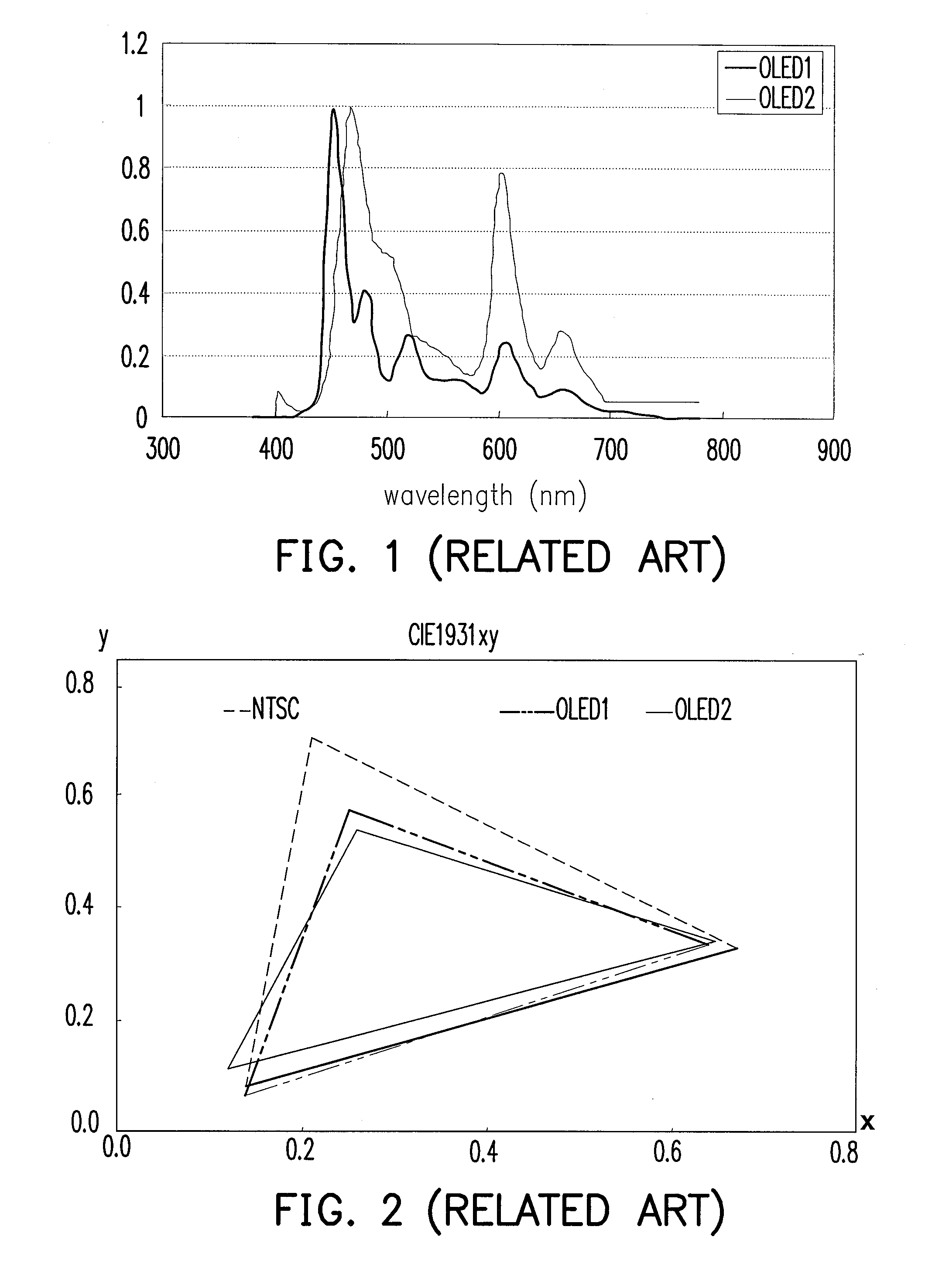
Obviously, when the organic electroluminescent devices OLED-1 and OLED-2 of the Eastman Kodak Company are used as the backlight sources, problems of poor color saturations and undesired color coordinates of the white color are occurred.

Method used


Image

  • Liquid crystal display
  • Liquid crystal display
  • Liquid crystal display

Examples


Embodiment Construction

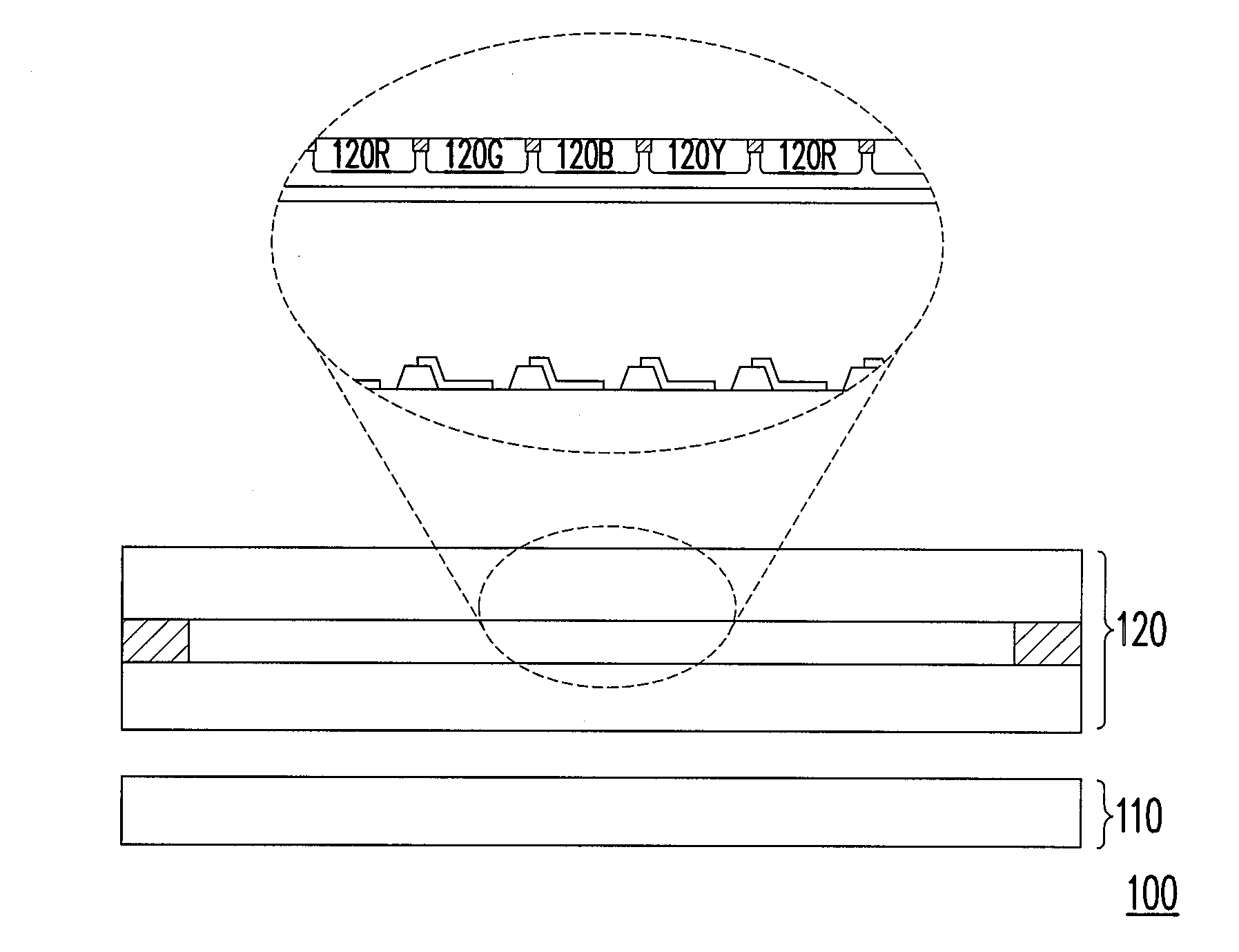
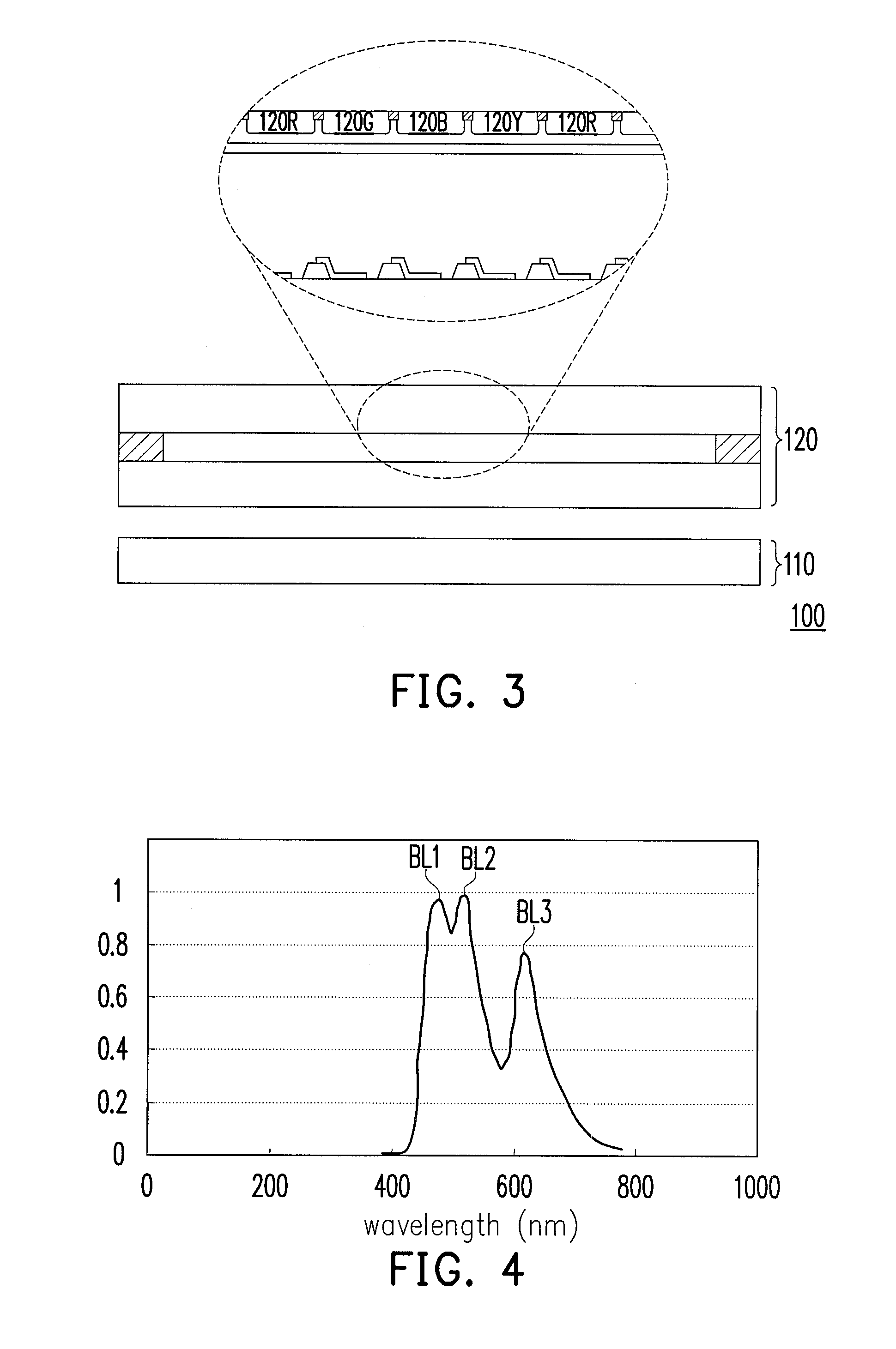
[0027]FIG. 3 is a schematic diagram illustrating a liquid crystal display (LCD) according to an embodiment of the invention. FIG. 4 is a diagram illustrating a spectrum of a backlight source of FIG. 3. Referring to FIG. 3 and FIG. 4, the LCD 100 of the present embodiment includes a backlight source 110 and a LCD panel 120. The backlight source 110 is, for example, an organic electroluminescent device, and a spectrum of the backlight source 110 has relative relative maximum brightness peaks at wavelength between 460 nm and 480 nm, between 505 nm and 525 nm, and between 610 nm and 630 nm, as that shown in FIG. 4. In the present embodiment, the backlight source 110 has a relative maximum brightness peak BL1 when the wavelength is between 460 nm and 480 nm, the backlight source 110 has a relative maximum brightness peak BL2 when the wavelength is between 505 nm and 525 nm, the backlight source 110 has a relative maximum brightness peak BL3 when the wavelength is between 610 nm and 630 n...


PUM

PropertyMeasurementUnit
wavelengthaaaaaaaaaa

Abstract

A liquid crystal display including a backlight unit and a liquid crystal display panel is provided. A spectrum of the backlight unit has relative relative maximum brightness peaks at wavelength between 460 nm to 480 nm, between 505 nm to 525 nm, and between 610 nm to 630 nm. The liquid crystal display panel is disposed above the backlight unit. The liquid crystal display panel has a red color filter layer (Rx, Ry, RY), a green color filter layer (Gx, Gy, GY), a blue color filter layer (Bx, By, BY) and a yellow color filter layer (Yx, Yy, YY), wherein under the backlight source, the red color filter layer, the green color filter layer, the blue color filter layer and the yellow color filter layer satisfy following conditions: Rx≧0.654; Ry≦0.330; Gx≦0.253; Gy≧0.605; Bx≦0.136; By≦0.146; Yx≦0.408; Yy≦0.534; 0.83≦RY / GY≦0.87; 0.86≦GY / BY≦0.92; 0.83≦BY / YY≦0.87 and 1.5≦YY / RY≦1.55.

Description

CROSS-REFERENCE TO RELATED APPLICATION[0001]This application claims the priority benefit of Taiwan application serial no. 99132039, filed on Sep. 21, 2010. The entirety of the above-mentioned patent application is hereby incorporated by reference herein and made a part of this specification.BACKGROUND[0002]1. Field of the Invention[0003]The invention relates to a liquid crystal display. Particularly, the invention relates to a liquid crystal display having a good color saturation.[0004]2. Description of Related Art[0005]Since a liquid crystal display (LCD) has advantages of small size, high image quality, low power consumption, and no irradiation, etc., it replaces a conventional cathode ray tube (CRT) display and becomes popular in the display market. However, compared to the CRT display, the LCD generally requires a backlight source for displaying images. The backlight source used by the LCD includes a cold-cathode fluorescent lamp (CCFL) backlight source and a light emitting diod...

Claims


Application Information

Patent Timeline
Patent Type & Authority Applications(United States)
IPC IPC(8): G02F1/1335
CPCG02F1/133514G02F2001/133624H01L51/5036G02F1/133606G02F1/133621G02F1/1336G02F1/133624H10K50/125
Inventor WANG, YING-LILIU, YUN-ILIN, CHUN-LIANGCHEN, CHIEN-KAILIAO, CHEN-HSIEN
Owner AU OPTRONICS CORP
Learn More