Friction drive lift

Active Publication Date: 2012-03-29
HANDICARE STAIRELEVATORS
View PDF21 Cites 8 Cited by
  • Summary
  • Abstract
  • Description
  • Claims
  • Application Information

AI Technical Summary

Benefits of technology

[0007]It is an object of the present invention to eliminate at least

Problems solved by technology

Drawback of these known stair lifts i

Method used


Image

  • Friction drive lift
  • Friction drive lift
  • Friction drive lift

Examples


first embodiment

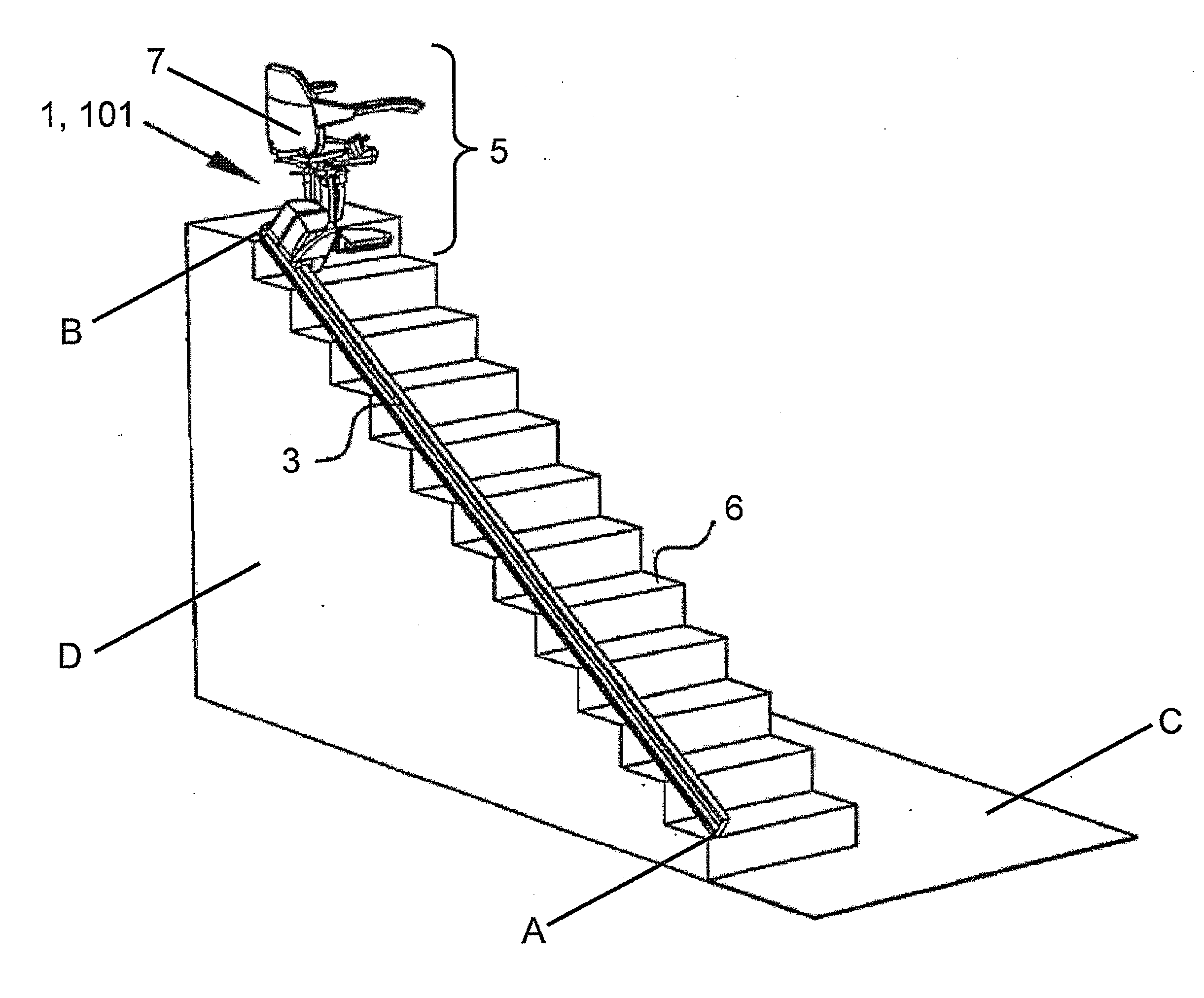
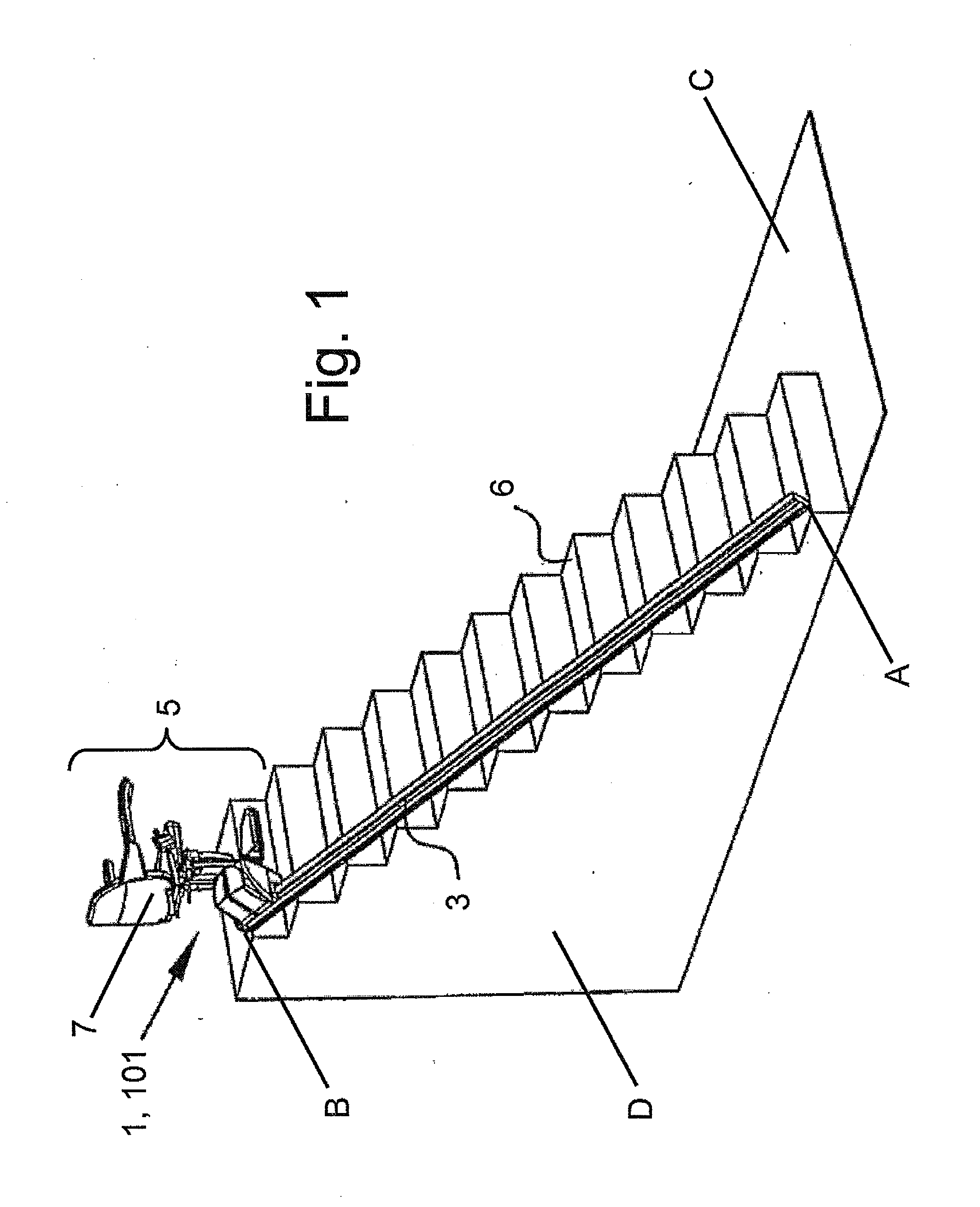
[0075]FIG. 1 shows a stair lift 1 according to the invention and comprises a guide 3 and a carriage 5. The guide 1 is arranged along a staircase 6. The staircase may be used by a person to transport himself from a start point to an end point or vice versa. In FIG. 1 it is shown that the guide 1 is arranged from start point A to start point B. When the person is handicapped or for other reasons unable to use the staircase 6, the person may use the stair lift 1 to be transported from start point A to end point B or vice versa. In this embodiment the stair lift 1 further comprises a load carrier 7 in the form of a seat. The load carrier 7 may be used by the person to sit on. Particularly, when the person is seated in the load carrier 7 the person may be transported between start point A and end point B or vice-versa. Alternatively, the load carrier 7 is a flat platform for carrying a wheel chair or goods. In FIG. 1 the guide 3 is shown as a straight rail.

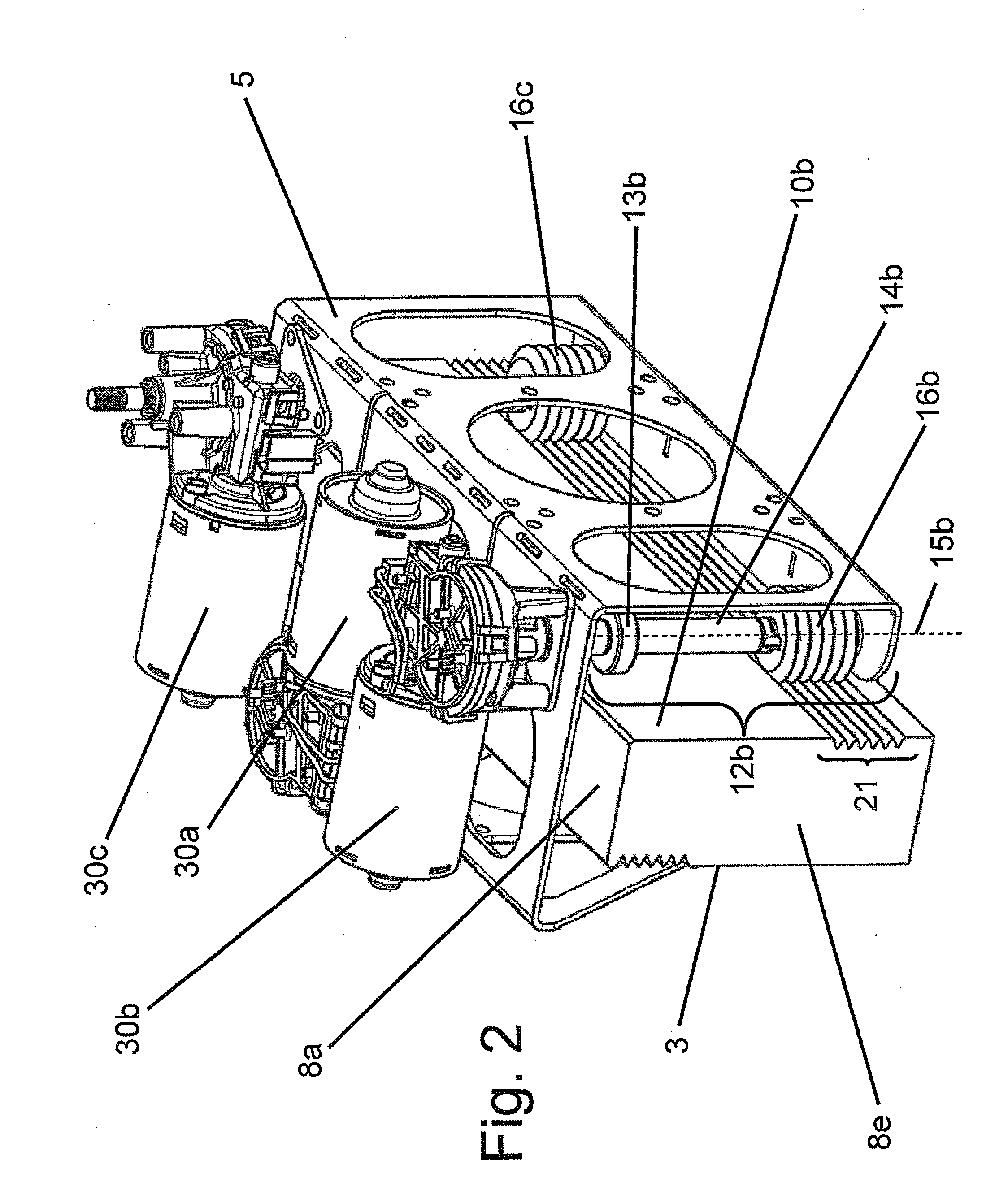
[0076]FIG. 2 shows a perspectiv...

second embodiment

[0100]In this second embodiment the frame 105 is provided with four rollers. Two rollers, being a first roller 112a and a fourth roller 112d, are arranged in frictional engagement with the first side running surface 10a. This can be seen best in FIG. 9. Two other rollers, being a second roller 112b and a third roller 112c are arranged in frictional engagement with the second side running surface 10b. These can be seen best in FIG. 11. Note, that the first side running surface 10a and the second side running surface 10b are opposing sides. Therefore, the first roller 112a and the fourth roller 112d are arranged on opposing sides with respect to the second roller 112b and the third roller 112d. The fact that four rollers are arranged with two rollers on opposing sides has as advantage that forces and moments of forces originated by the load carrier 7 can be distributed safely via the rollers 112a, 112b, 112c, 112d to the guide 3 which will be explained below.

[0101]The load carrier 7 i...


PUM


Abstract

A stair lift for transporting a load includes a longitudinal guide having a first side running surface and a second side running surface opposing the first side running surface; and a carriage which is transportable along the guide and provided with rollers for guiding the carriage along the guide. The rollers include a first roller having a first roller peripheral friction surface which is in frictional engagement with the first side running surface for guiding the carriage along the guide and a second roller having a second roller peripheral friction surface which is in frictional engagement with the second side running surface for guiding the carriage along the guide. The first roller friction surface is provided with a first roller member, and the first side running surface is provided with a longitudinal first side running surface member which fits complementary with the first roller member.

Description

CROSS-REFERENCE TO RELATED APPLICATIONS[0001]This application claims the benefit of Netherlands Application No. 2005398, filed Sep. 27, 2010, the contents of which is incorporated by reference herein.FIELD OF THE INVENTION[0002]The present invention relates to a stair lift for transporting a load.BACKGROUND OF THE INVENTION[0003]Stair lifts are well known and are particularly used for transporting loads such as persons and / or goods up or down over a stairs by being carried on a chair or a platform. In general a stair lift comprises of a guide or rail to be attached along a staircase and a motorized carriage or trolley which carries and guides the load along the rail.[0004]Stair lifts may be driven by friction drive rollers which are in frictional engagement with the guide. These have proven to be less expensive than form fitted drive means such as sprocket and chains or rack and pinion.[0005]For example, a stair-climbing device is known from patent publication EP-0,881,188-A1. This ...

Claims


Application Information

Patent Timeline
IPC IPC(8): B66B9/08
CPCB66B9/08B66B9/0846B66B9/0815
Inventor ROSENTHAL, DOV
Owner HANDICARE STAIRELEVATORS
Why Eureka
Try Eureka