Capture time reduction for correction of display non-uniformities

a technology of display non-uniformity and capture time reduction, which is applied in the field of system for reducing mura defects in displayed images, can solve problems such as mura defects on display, unsatisfactory modulation of luminance, and mura defects appearing

Inactive Publication Date: 2012-03-29
SHARP LAB OF AMERICA INC
View PDF11 Cites 38 Cited by
  • Summary
  • Abstract
  • Description
  • Claims
  • Application Information

AI Technical Summary

Problems solved by technology

Such inspection includes, for example, pixel-based defects and area-based defects.
The quality of the resulting inspection is dependent on the individual operator which are subjective and prone to error.
For example, when an intended flat region of color is displayed, various imperfections in the display components may result in undesirable modulations of the luminance.
There are many stages in the manufacturing process that may result in mura defects on the display.
Mura defects may appear as low frequency, high-frequency, noise-like, and / or very structured patterns on the display.
In general, most mura defects tend to be static in time once a display is constructed.
However, some mura defects that are time dependent include pixel defects as well as various types of non-uniform aging, yellowing, and burn in.
The LCD panel itself may be a source of mura defects because of non-uniformity in the liquid crystal material deposited on the glass.
Yet another source of mura defects is pixel noise, which is primarily due to variations in the localized driving circuitry (e.g., the thin film transistors) and is usually manifested as a fixed pattern noise.
The continual quality improvement in display components reduces mura defects but unfortunately mura defects still persist even on the best displays.
Referring to FIG. 1, identification of mura defects is not straightforward because the source of the mura arise in different luminance domains.
Unfortunately, the data displayed on the image domain of the image in the LCD code value space is neither linear nor log luminance.

Method used


Image

  • Capture time reduction for correction of display non-uniformities
  • Capture time reduction for correction of display non-uniformities
  • Capture time reduction for correction of display non-uniformities

Examples


Embodiment Construction

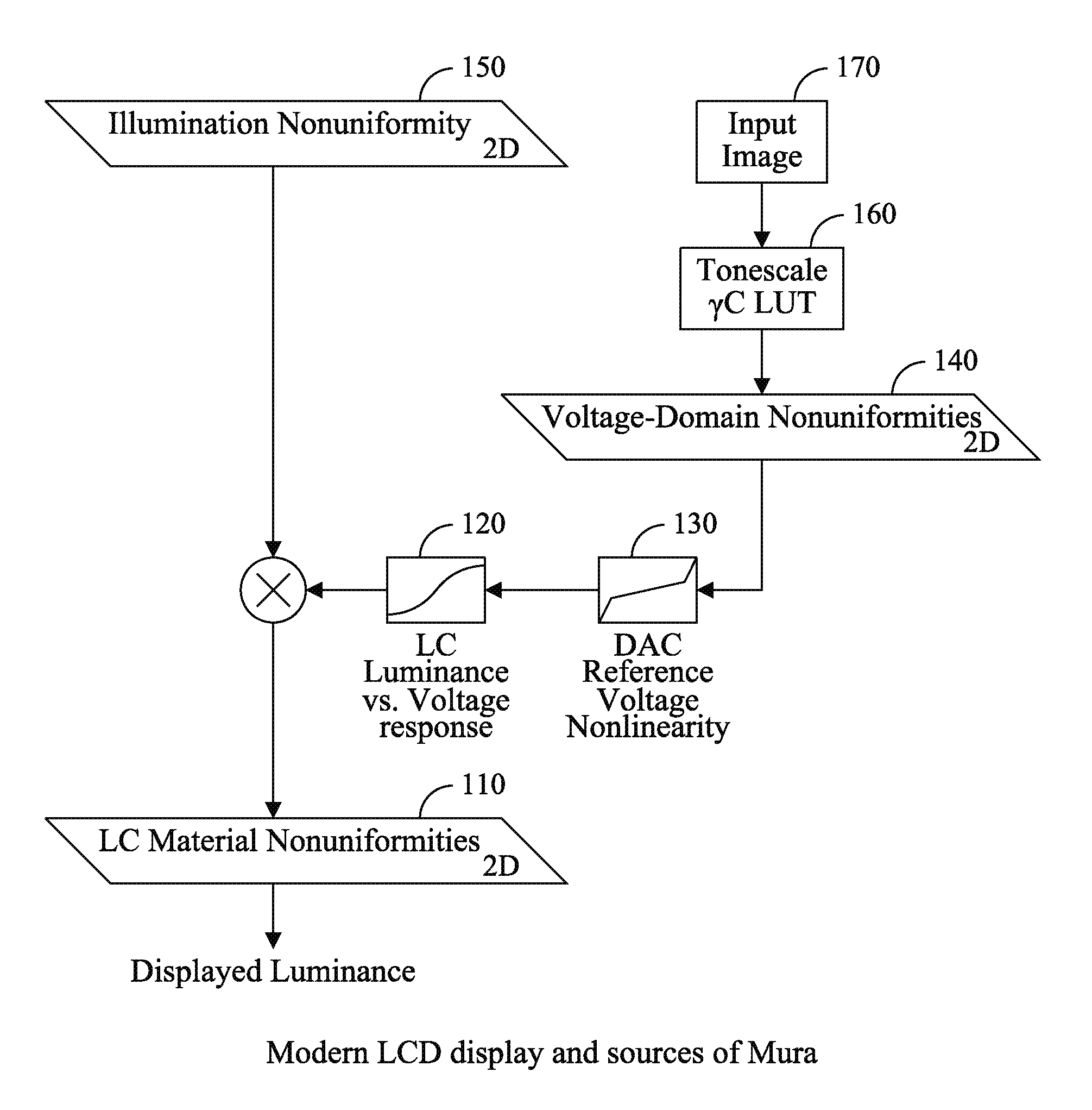
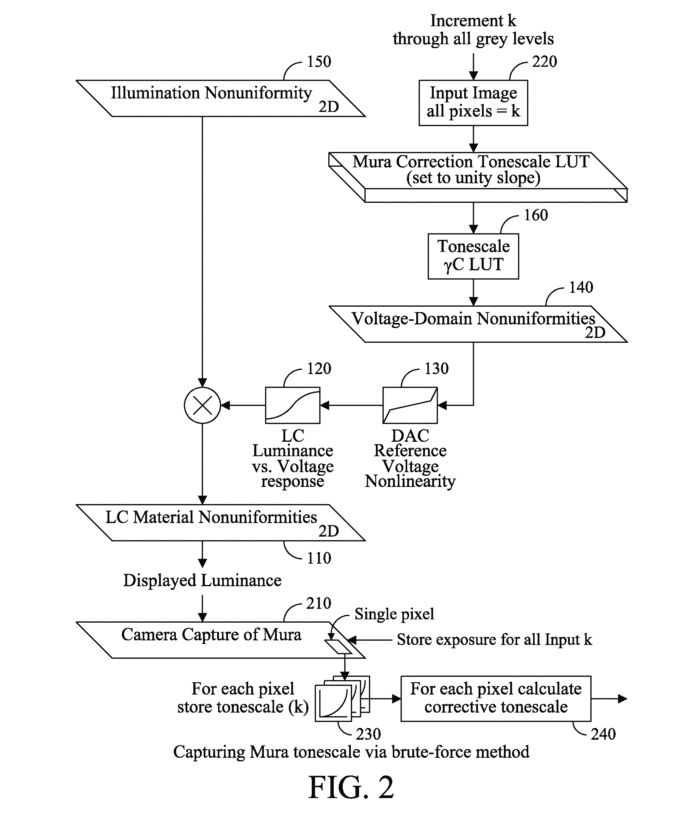
[0022]Existing techniques for correcting display non-uniformity are based upon multiple camera captures in order to cover the whole display luminance range. The more camera captures that are required for the technique, the more time that is required to obtain the desired measurements. While suitable for low-volume characterization, when there are time limitations in a production environment this characterization technique requires a significant amount of time. Accordingly, the brute force technique of measuring mura data for each code value of the display tone scale (e.g., 256 for an 8 bit display) may require longer to complete than the time available. Similarly, an interpolative approach for Mura measurements for only a subset of the code values (e.g., on the set [31, 63, 95, 127, 191, 255] for luminance correction) uses a smaller set but is generally not an optimal selection of code value. In addition, the time to obtain suitable Mura measurements is code value dependent. For exa...


PUM


Abstract

A display includes a plurality of gray levels being provided to a plurality of pixels of the display and illuminating each of the pixels with the plurality of gray levels. The display applying corrective data for the pixels so as to reduce the mura effects of the display for the plurality of gray levels, wherein a selection of code values for the corrective data is determined based upon a minimization of an error function.

Description

CROSS-REFERENCE TO RELATED APPLICATIONS[0001]None.BACKGROUND OF THE INVENTION[0002]The present invention relates to a system for reducing mura defects in a displayed image in an efficient manner.[0003]The number of liquid crystal displays, electroluminescent displays, organic light emitting devices, plasma displays, and other types of displays are increasing. The increasing demand for such displays has resulted in significant investments to create high quality production facilities to manufacture high quality displays. Despite the significant investment, the display industry still primarily relies on the use of human operators to perform the final test and inspection of displays. The operator performs visual inspections of each display for defects, and accepts or rejects the display based upon the operator's perceptions. Such inspection includes, for example, pixel-based defects and area-based defects. The quality of the resulting inspection is dependent on the individual operator w...

Claims


Application Information

Patent Timeline
Patent Type & Authority Applications(United States)
IPC IPC(8): G09G5/10
CPCG09G5/10G09G2320/0233G09G2360/147G09G2320/0295G09G2320/0693G09G2320/0285
Inventor SU, YEPINGFENG, XIAOFAN
Owner SHARP LAB OF AMERICA INC
Why Eureka
Try Eureka