
Liquid crystal display

a liquid crystal display and vertical alignment technology, applied in non-linear optics, instruments, optics, etc., to achieve the effect of improving alignment uniformity

Inactive Publication Date: 2012-03-29
STANLEY ELECTRIC CO LTD
View PDF5 Cites 18 Cited by
  • Summary
  • Abstract
  • Description
  • Claims
  • Application Information

AI Technical Summary

Benefits of technology

The present invention provides a liquid crystal display device that can lower the frame frequency while maintaining display uniformity in the case of driving a vertical alignment liquid crystal display device by multiplex driving under a condition where the pretilt angle is close to 90°. This is achieved by designing a liquid crystal layer with a pretilt angle set to 89.7° or more and less than 90°, and disposing the electrodes in a way that the alignment direction of the liquid crystal molecules at the center of the layer is 0° or more and less than 90°. The invention also includes a liquid crystal display device with a plurality of openings in the electrodes, where the openings have a specific alignment direction with the pretilt angle. The technical effects of the invention include improved alignment uniformity and reduced frame frequency.

Problems solved by technology

These dark regions can be eliminated by increasing the frame frequency, but this is contradictory to the demands of lowering the frame frequency.

Method used


Image

  • Liquid crystal display
  • Liquid crystal display
  • Liquid crystal display

Examples


example 1

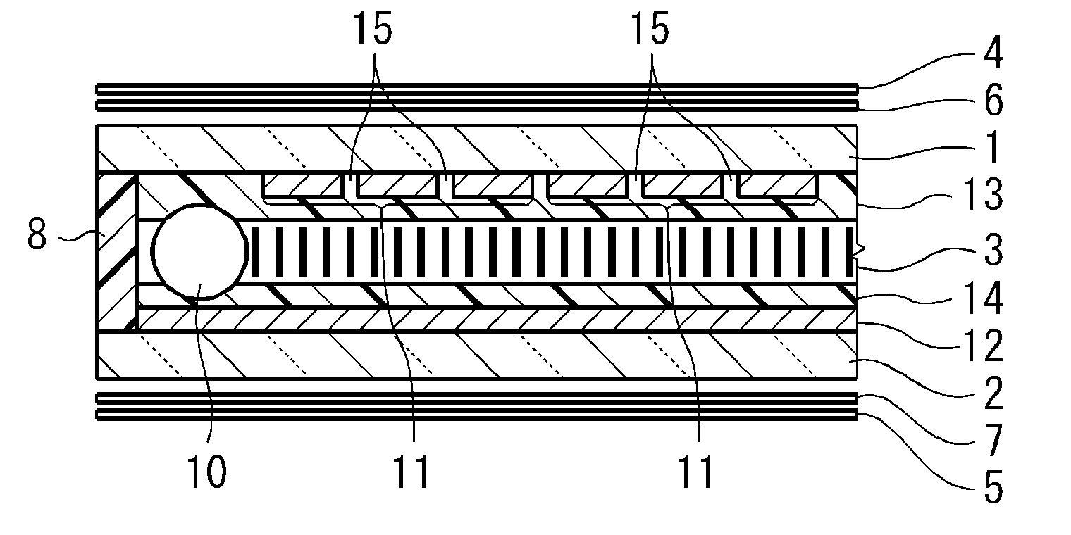
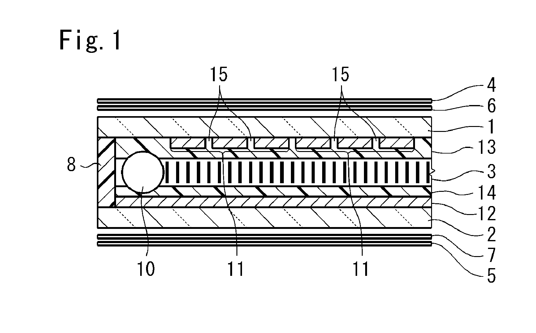
[0068]Prepared was a segment display-type liquid crystal display device in which the first electrode 11 and the second electrode 12 in the liquid crystal display device shown in FIG. 1 were structured for performing segment display including a plurality of arbitrary shapes such as text, seven segments, and design shapes. Note that the first electrode 11 corresponds to a common electrode, and the second electrode 11 corresponds to a segment electrode.

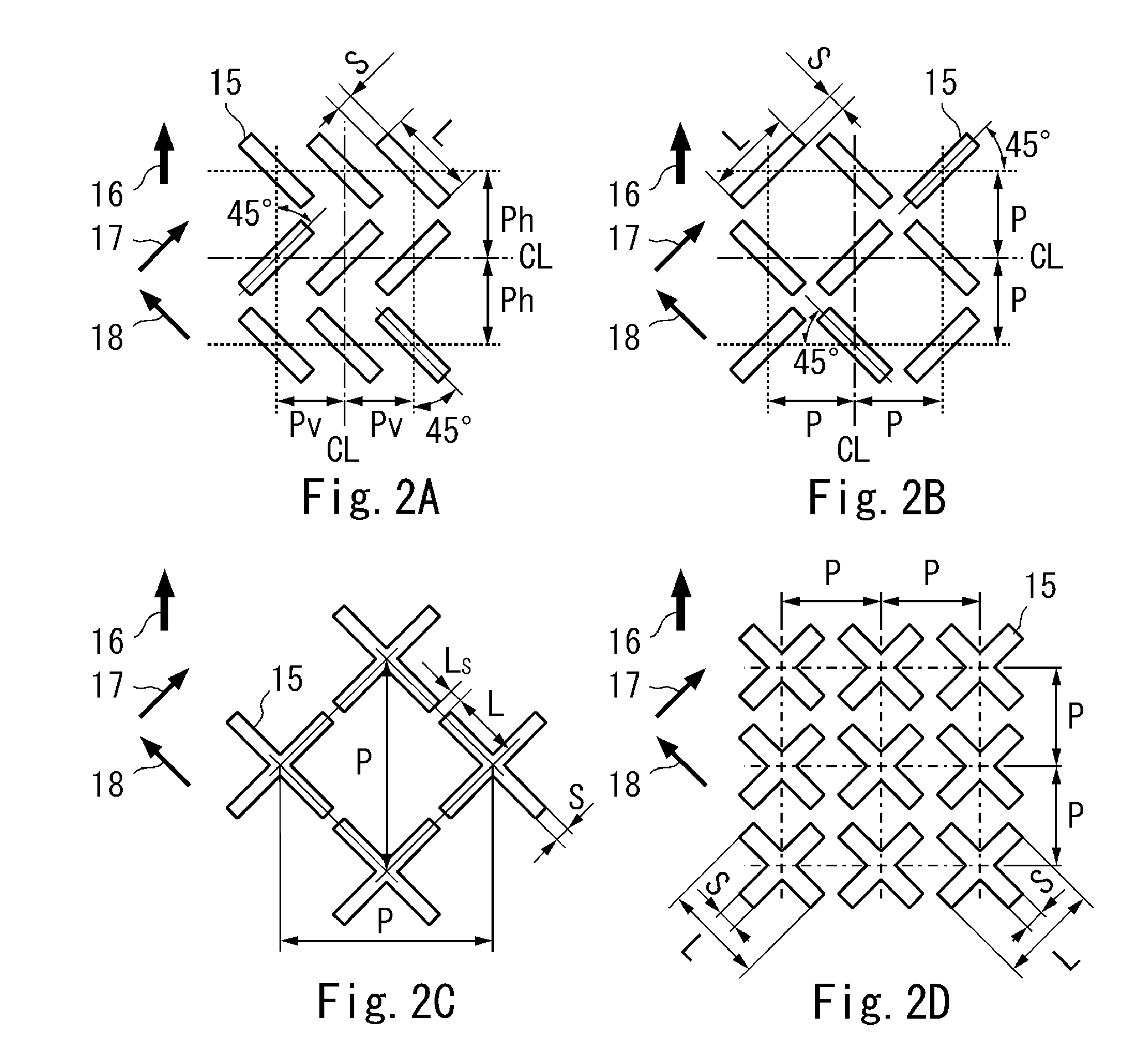
[0069]In Example 1, the respective openings 15 shown in foregoing FIG. 2A or FIG. 2B were provided to the first electrode 11 (common electrode) within the pixel. Note that the respective openings 15 can also be provided to the second electrode 12 (segment electrode). Moreover, if there are a plurality of segment display parts, it is not necessary to provide the respective openings 15 to one electrode in all of the respective segment display parts. Specifically whether to provide the respective openings 15 to the first electrode 11 or the...

example 2

[0075]In the foregoing liquid crystal display device shown in FIG. 1, prepared was a liquid crystal display device in which the size of one pixel is 0.42 mm square and the gap between the stripe-shaped electrodes is 0.03 mm in a dot matrix electrode structure where the first electrode 11 and the second electrode 12 are formed in a stripe shape and crisscrossed. In addition, a liquid crystal display device having the segment display-type electrode structure shown in Example 1 was also prepared.

[0076]The first electrode 11 was provided with a plurality of cross-shaped openings 15 shown in foregoing FIG. 2C in the pixel. With the respective openings 15, the center of gravity thereof was respectively disposed in a checkered shape relative to the vertical / horizontal direction of the liquid crystal display device. In Example 2, since the respective openings 15 were provided to the first electrode 11 of the first substrate 1 irrelevant to the arrangement of the dot matrix pixels, the arran...

example 3

[0082]In the foregoing liquid crystal display device shown in FIG. 1, prepared was a liquid crystal display device having a segment display-type electrode structure as with Example 1. The first electrode 11 of the first substrate 1 (common substrate) was provided with the respective cross-shaped openings 15 shown in foregoing FIG. 21) in the pixel. With the respective openings 15, the center of gravity thereof was respectively disposed in a checkered shape relative to the vertical / horizontal directions in planar view. Note that, as with the case of Example 1, the respective openings are arranged on one electrode in the display parts, but it is not necessary to provide openings to the same electrode in all display parts, and the openings can also be arranged on one or the other electrode for each display part.

[0083]The size of the openings of the liquid crystal display device of Example 3 was set as follows. Specifically, S was fixed to 0.007 mm and L was fixed to P−0.025 mm, and P w...


PUM

PropertyMeasurementUnit
pretilt angleaaaaaaaaaa
angleaaaaaaaaaa

Abstract

A liquid crystal display includes a first substrate having a first electrode on one surface side, a second substrate having second electrode on one surface side and placed opposite to the first substrate. A liquid crystal layer having a pretilt angle of 89.7° or more and less than 90° is disposed between the first and second electrodes. The first and second electrodes respectively form a pixel in opposing areas. The first electrode includes rectangularly shaped openings disposed with regularity in the pixel in a planar view. The openings include first and second openings with longitudinal directions respectively facing first and second directions, the second direction different from the first direction. The angle formed by the longitudinal directions of the first and second openings, and an alignment direction of liquid crystal molecules at the substantial center of the liquid crystal layer is 0° or more and less than 90°.

Description

BACKGROUND OF THE INVENTION[0001]1. Field of the Invention[0002]The present invention relates to a vertical alignment liquid crystal display device which is driven by multiplex driving.[0003]2. Description of the Background Art[0004]A liquid crystal display device is broadly used as an information display unit in various electronic devices for consumer or automobile use. In General, a liquid crystal display device is configured by disposing a liquid crystal layer made of a liquid crystal material between two substrates that are placed opposite each other with a gap of roughly several micrometers. As one type of this kind of liquid crystal display device, a vertical alignment liquid crystal display device is known. A vertical alignment liquid crystal display device comprises, as its main components, liquid crystal cells of a VA mode in which liquid crystal molecules are aligned substantially vertically relative to the surface of the respective substrates within the liquid crystal lay...

Claims


Application Information

Patent Timeline
Patent Type & Authority Applications(United States)
IPC IPC(8): G02F1/1337
CPCG02F1/133707G02F1/1393G02F2001/134318G02F2001/133773G02F2001/133746G02F1/133746G02F1/133773G02F1/134318
Inventor IWAMOTO, YOSHIHISAKATANO, KUNIHIKO
Owner STANLEY ELECTRIC CO LTD
Learn More