Interspinous implants and methods for implanting same

a technology of interspinous implants and implants, which is applied in the field of spinal implants, can solve the problems of spinal canal narrowing and spinal cord compression, pain and numbness in the back and legs, weakness and/or loss of balance,

Active Publication Date: 2012-03-29
SPINAL SIMPLICITY
View PDF12 Cites 69 Cited by
  • Summary
  • Abstract
  • Description
  • Claims
  • Application Information

AI Technical Summary

Benefits of technology

[0022]In still one more embodiment, the subject technology is directed to a device for measuring percutaneously an optimum size of an interspinous implant. The measuring device includes a proximal deployment portion including a plunger tube carrying a rod, a distal measuring assembly including four connected arms pivotally connected at four coupling joints, a central shaft connected to the rod of the plunger tube a proximal end and connected to the coupling joint on

Problems solved by technology

Over time, the ligaments and bone that surround the spinal canal can thicken and harden, resulting in a narrowing of the spinal canal and compression of the spinal cord.
This condition is called spinal stenosis, which results in pain and numbness in the back and legs, weakness and/or a lo

Method used


Image

  • Interspinous implants and methods for implanting same
  • Interspinous implants and methods for implanting same
  • Interspinous implants and methods for implanting same

Examples


Embodiment Construction

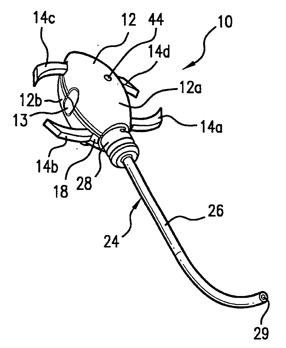
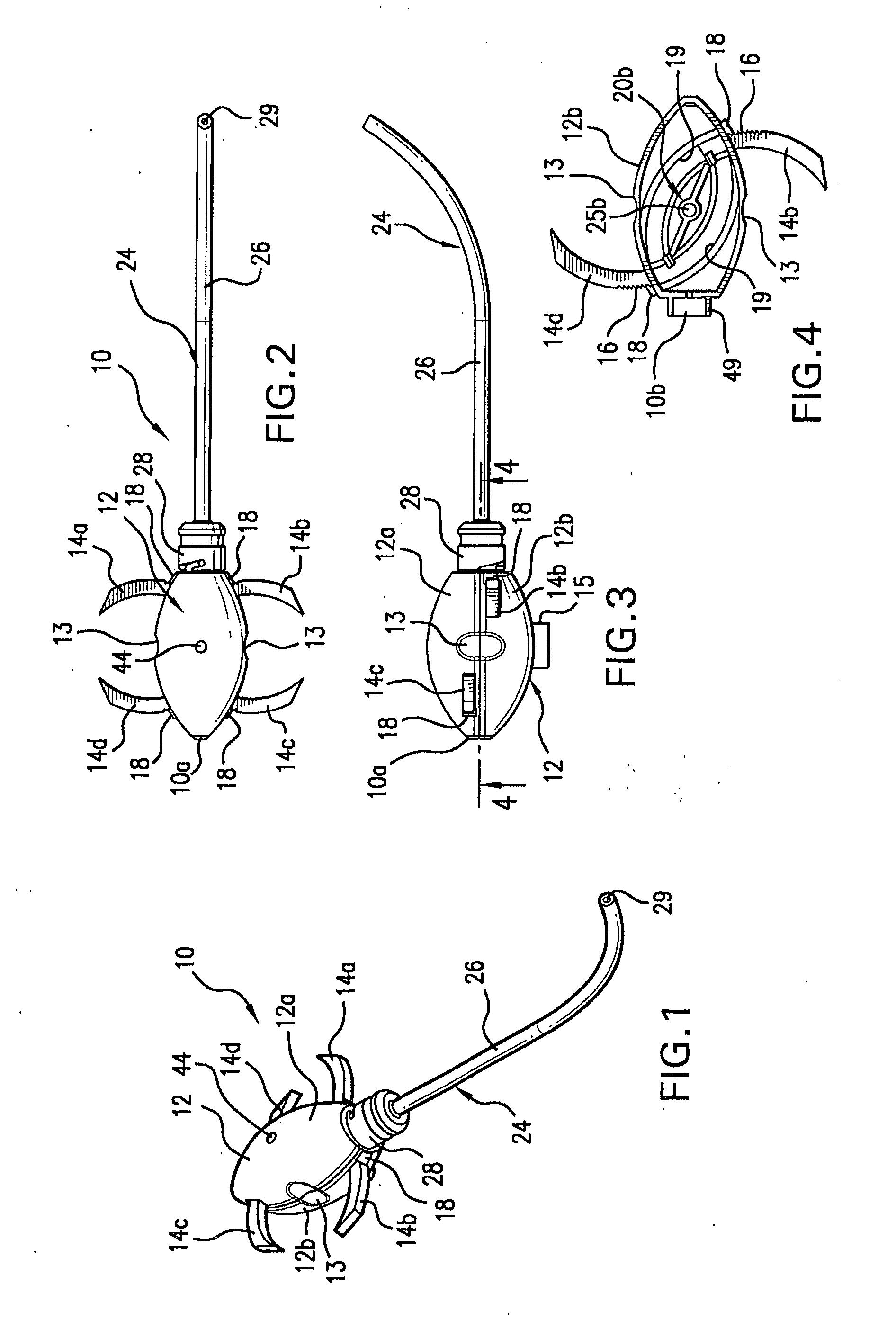
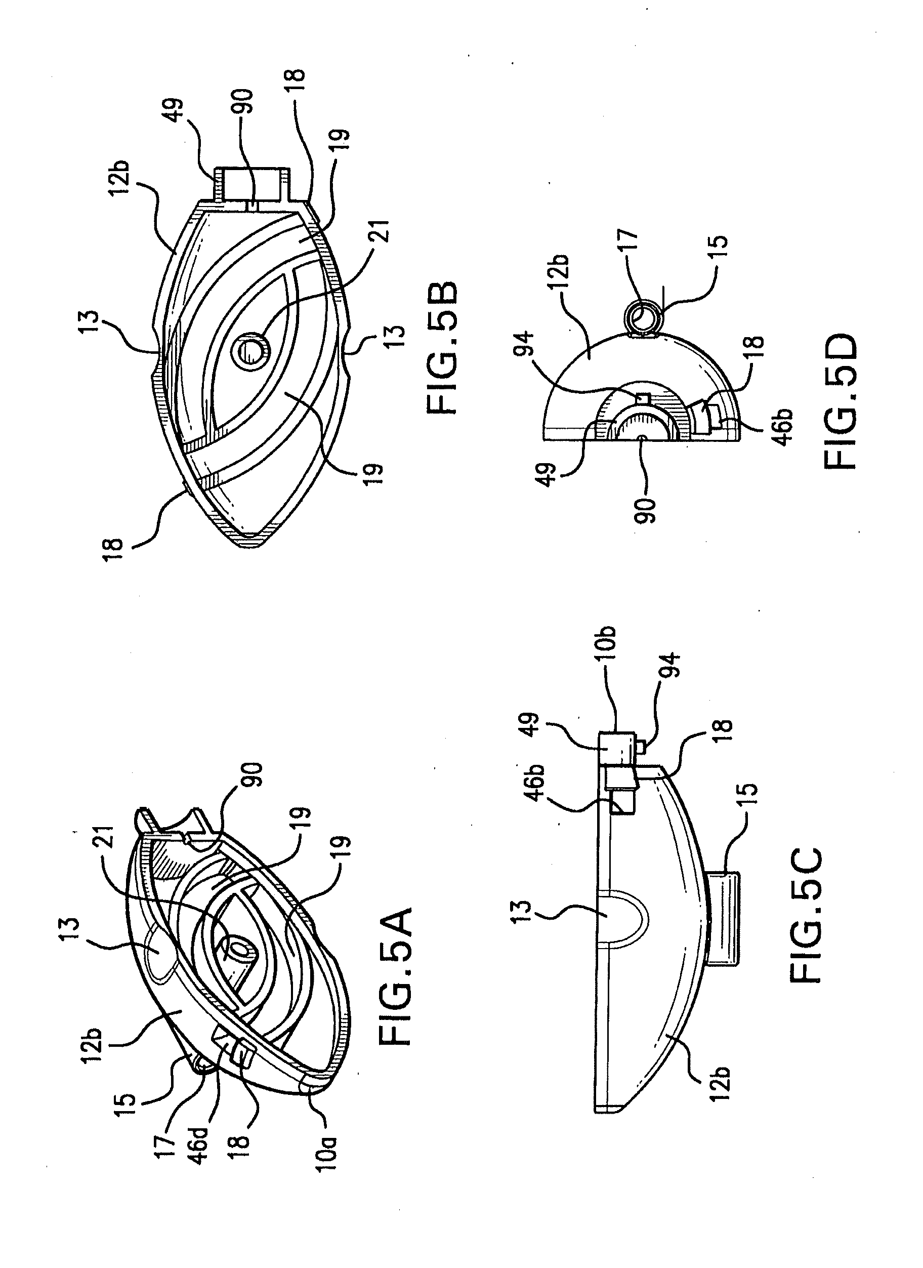
[0068]The present invention overcomes many of the prior art problems associated with implants to relieve spinal stenosis. The advantages, and other features of the system disclosed herein, will become more readily apparent to those having ordinary skill in the art from the following detailed description of certain preferred embodiments taken in conjunction with the drawings which set forth representative embodiments of the present invention and wherein like reference numerals identify similar structural elements. All relative descriptions herein such as horizontal, vertical, left, right, upper, and lower are with reference to the Figures, and not meant in a limiting sense. For reference, proximal is generally the area or portion adjacent or near the surgeon whereas distal refers to the portion remote or away from the surgeon.

Spinal Implant

[0069]Referring now FIG. 1, there is illustrated an interspinous implant constructed in accordance with a preferred embodiment of the subject inve...


PUM


Abstract

A spinal implant for treating lumbar spinal stenosis or as an adjunct to spinal fusion. The implant includes a body portion having an interior cavity. A plurality of locking wings are adapted and configured to move between a stowed position retracted within the interior cavity of the body portion and a deployed position extended from the interior cavity of the body portion. In the deployed position, the wings fix the implant in a selected interspinous space. A cable and wheel arrangement moves the plurality of locking wings from the stowed position to the deployed position and a ratchet/pawl assembly prevents backward movement of the wings.

Description

CROSS-REFERENCE TO RELATED APPLICATION[0001]This application claims priority to the following applications: U.S. patent application Ser. No. 11 / 743,086, filed May 1, 2007; U.S. Provisional Patent Application No. 60 / 959,799, filed Jul. 16, 2007; U.S. Provisional Patent Application No. 60 / 961,780, filed Jul. 24, 2007; U.S. Provisional Patent Application No. 61 / 000,831, filed Oct. 29, 2007; and U.S. Provisional Patent Application No. 61 / 001,430, filed Nov. 1, 2007, each of which is incorporated herein by reference.BACKGROUND OF THE INVENTION[0002]1. Field of the Invention[0003]The subject invention is directed to spinal implants, and more particularly, to an interspinous implant with deployable wings for treating lumbar spinal stenosis, methods for the percutaneous implantation of the interspinous implant, and techniques for determining an appropriate size of the interspinous implant.[0004]2. Description of Related Art[0005]The spine consists of a column of twenty-four vertebrae that e...

Claims


Application Information

Patent Timeline
IPC IPC(8): A61B17/70
CPCA61B17/025A61B17/7065A61B2019/461A61B2017/90A61B2017/0256A61B2090/061A61B17/90
Inventor HESS, HAROLD
Owner SPINAL SIMPLICITY
Why Eureka
Try Eureka