Fusion cage with in-line single piece fixation

a single-piece fixation and fusion cage technology, applied in the field of fusion cages with single-piece fixation, can solve problems such as patient discomfort, and achieve the effect of promoting fusion and small incisions

Active Publication Date: 2012-03-29
DEPUY SYNTHES PROD INC
View PDF29 Cites 182 Cited by
  • Summary
  • Abstract
  • Description
  • Claims
  • Application Information

AI Technical Summary

Benefits of technology

[0019]The device of the present invention allows for a smaller incision and access site, and the in-line nature of the staple also frees the surgeon from having to insert the staple at a high angle through sometimes challenging approaches.
[0020]Therefore, the present invention is advantageous because it allows for fixation of the cage to each of the vertebral bodies via a single staple. The staple is preferably designed to provide an essentially zero-profile device. This staple may be inserted fully through or partially through a side wall of the cage and into the adjacent vertebral bodies. Further, these staples may be designed to provide compression to the graft held within the cage and thereby promote fusion.

Problems solved by technology

Often times, the plate may be considered to be too proud and its profile can sometimes cause patient discomfort and may be related to dysphasia.

Method used


Image

  • Fusion cage with in-line single piece fixation
  • Fusion cage with in-line single piece fixation
  • Fusion cage with in-line single piece fixation

Examples


Embodiment Construction

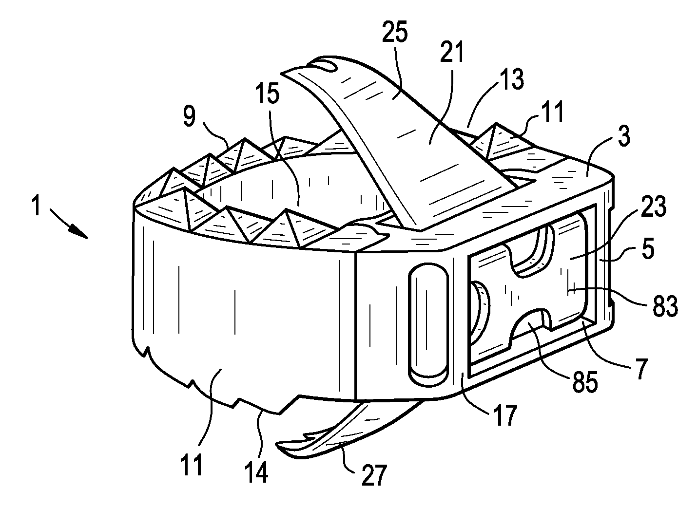
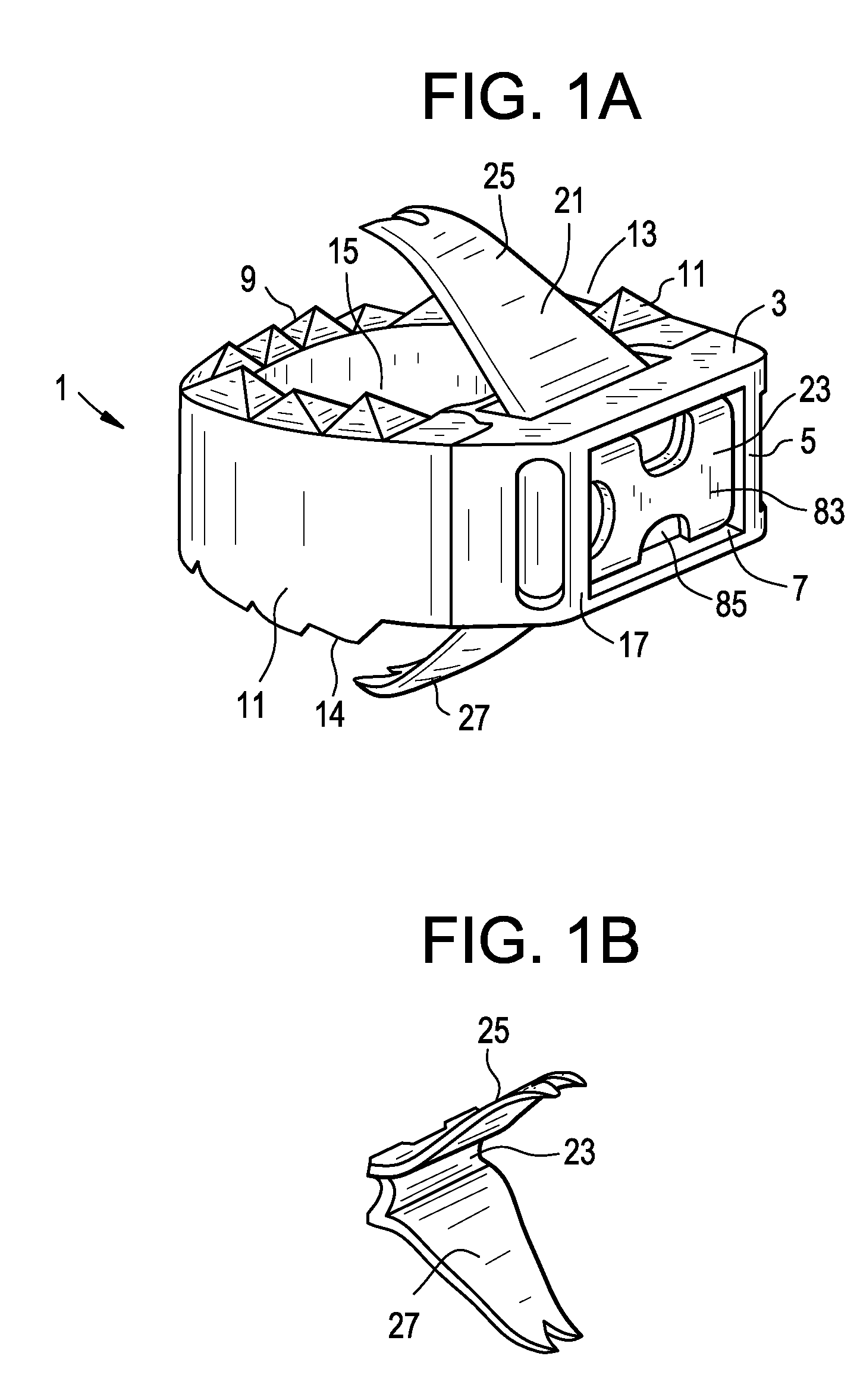
[0041]Now referring to FIGS. 1a and 1b, there is provided (claim 1) a zero-profile intervertebral fusion device comprising:[0042]a) an intervertebral fusion cage 1 comprising an anterior wall 3 having an anterior face 5 having a recess 7 therein, a posterior wall 9, a pair of side walls 11 connecting the anterior and posterior walls, an upper surface 13, a lower surface 14, and a through hole 15 extending from the upper surface to the lower surface, the cage having an anterior end 17,[0043]b) a staple 21 comprising a first crossbar 23 and first 25 and second 27 tynes extending therefrom,

wherein at least a portion of the first crossbar of the staple is disposed in the recess in the anterior face of the anterior wall, and

wherein the first tyne extends above the upper surface of the cage and the second tyne extends below the bottom surface of the cage,

wherein the anterior face is the anterior end of the cage.

[0044]This cage of FIG. 1 differs from that of Bramlet (FIGS. 1 and 2) in that...


PUM


Abstract

Methods for securing a intervertebral cage to one or more levels of the spine with fixation. The fixation, which is typically a staple, is intended to be driven perpendicular to the proximal face of the cage and in-line with the inserter. After the cage is placed and positioned according to surgeon preference, a single piece fixation clip is then deployed and fixed in a manner that produces a zero-profile device.

Description

RELATED APPLICATIONS[0001]This application claims priority from U.S. Ser. No. 61 / 385,959, filed on Sep. 23, 2010, and entitled “Stand Alone Intervertebral Fusion Device ” (DEP6341USPSP), and is related to non-provisional U.S. Ser. No. ______, filed on even date, entitled “Stand Alone Intervertebral Fusion Device” (DEP6341USNP), the specifications of which are incorporated by reference in their entireties.[0002]This application claims priority from U.S. Ser. No. 61 / 466,309, filed on Mar. 22, 2011, and entitled “Novel Implant Inserter Having a Laterally-Extending Dovetail Engagement Feature” (DEP6392USPSP), and is related to non-provisional U.S. Ser. No ______, filed on even date, entitled “Novel Implant Inserter Having a Laterally-Extending Dovetail Engagement Feature” (DEP6392USNP), the specifications of which are incorporated by reference in their entireties.[0003]This application claims priority from U.S. Ser. No. 61 / 466,321, filed on Mar. 22, 2011, and entitled “Fusion Cage with ...

Claims


Application Information

Patent Timeline
Patent Type & Authority Applications(United States)
IPC IPC(8): A61F2/44
CPCA61F2002/30161A61B2017/0641A61F2002/30484A61F2002/30579A61F2002/30604A61F2002/30607A61F2002/30616A61F2002/30774A61F2002/30787A61F2002/4625A61F2/4465A61F2/4611A61F2002/2835A61F2002/30092A61F2002/30509A61F2002/30518A61F2002/30576A61F2002/30841A61F2002/30843A61F2002/30904A61F2002/4475A61F2002/4623A61F2310/00017A61F2310/00023A61F2310/00029A61F2310/00161A61B17/0642A61B17/0682A61F2002/30196A61F2002/30507A61F2/4603A61F2002/30593A61F2/44A61B17/70A61F2/28
Inventor GAMACHE, THOMASCHILDS, JOSEPHPARSONS, MATTHEWFLAHERTY, KEVIN
Owner DEPUY SYNTHES PROD INC
Why Eureka
Try Eureka