Armature for rotary electric apparatus and manufacturing method for the same

a technology for rotary electric apparatuses and manufacturing methods, which is applied in the direction of manufacturing stator/rotor bodies, magnetic circuit rotating parts, and shape/form/construction of magnetic circuits, etc., which can solve the problems of insufficient high manufacturing cost, and apt small width of insulating film

Inactive Publication Date: 2012-04-05
ASMO CO LTD
View PDF6 Cites 19 Cited by
  • Summary
  • Abstract
  • Description
  • Claims
  • Application Information

AI Technical Summary

Benefits of technology

[0008]In view of the foregoing and other problems, it is an object of the present invention to produce an armature of a rotary electric apparatus, wherein a burr of a core sheet can be restricted from projecting at a corner of a laminated core, and an amount of an insulating material for forming an insulating film on the laminated core can be reduced. It is another object of the present invention to produce a manufacturing method of the armature of a rotary electric apparatus.

Problems solved by technology

Therefore, the width of the insulating film is apt to be small and insufficient at the corner portion.
Consequently, the application of the insulating material requires higher manufacturing cost.

Method used


Image

  • Armature for rotary electric apparatus and manufacturing method for the same
  • Armature for rotary electric apparatus and manufacturing method for the same
  • Armature for rotary electric apparatus and manufacturing method for the same

Examples


first embodiment

[0031]As follows, an armature of a rotary electric apparatus according to the first embodiment will be described with reference to FIGS. 1 to 7. In the present embodiment, the rotary electric apparatus includes a rotor core.

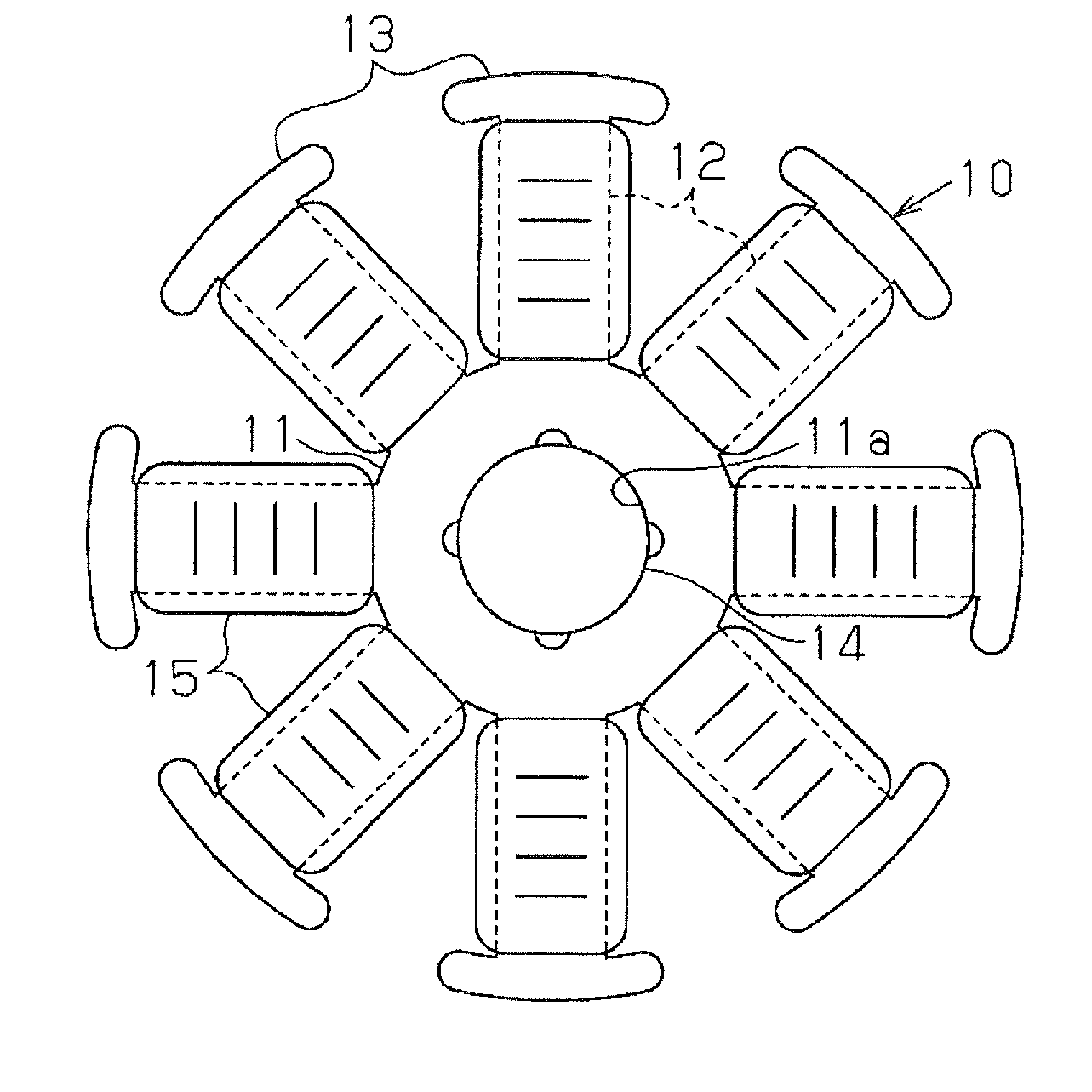
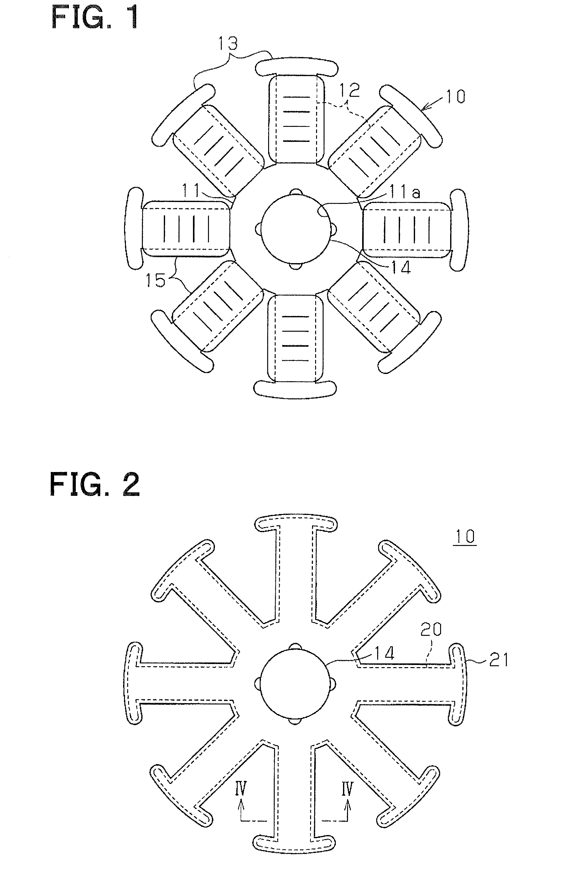
[0032]FIG. 1 shows the rotor core related to the present first embodiment. As shown in FIG. 1, the rotor core 10 includes a rotor center portion 11, eight teeth 12, and tip ends 13. The rotor center portion 11 is substantially in a circular shape on a planar view. The eight teeth 12 are radially extended from the rotor center portion 11. The tip ends 13 are respectively located at the ends of the teeth 12. Each of the tip ends 13 is substantially in an ellipse shape on a planar view. The rotor center portion 11 has an axial insertion hole 11a at the center. A rotation axis 14 is press-fitted in the axial insertion hole 11a. A winding 15 is wound on each of the teeth 12 in a winding direction perpendicular to a direction in which each tooth 12 are extended.

[0033]F...

second embodiment

[0047]Subsequently, the rotor core according to the second embodiment will be described with reference to FIGS. 8 to 10B. As shown in FIG. 8, an insulating film 42 is formed on the surface of the laminated core 41 of a rotor core 40 according to the present embodiment. As shown in FIGS. 8, 9A, 9B, the laminated core 41 includes a first core sheet 43a being a single sheet, multiple second core sheets 43b, and a third core sheet 43c being a single sheet. The first core sheet 43a, the second core sheets 43b, and the third core sheet 43c are laminated.

[0048]As shown in FIGS. 8, 9A, 9B, each teeth portion 44a of the first core sheet 43a has the width in the direction perpendicular to the extended direction in which the teeth portion 44a is extended. That is, each teeth portion 44a has the width in the horizontal direction on FIGS. 9A, 9B. The width of each teeth portion 44a of the first core sheet 43a is less than the width of each teeth portion 44b of the second core sheet 43b. The peri...

third embodiment

[0059]Subsequently, the rotor core according to the third embodiment will be described with reference to FIGS. 11, 12. As shown in FIG. 11, an insulating film 52 is formed on the surface of a laminated core 51 of a rotor core 50 according to the present embodiment. The laminated core 51 includes a first core sheet 53a, a second core sheets 53b, and a third core sheet (not shown) being laminated. In the present embodiment, the structure of the laminated core other than the shape of a burr 56a of the first core sheet 53a is substantially equivalent to that of the second embodiment.

[0060]Specifically, in present embodiment as shown in FIG. 11, the burr 56a of a teeth portion 54a of the first core sheet 53a extends in the horizontal direction in FIG. 11 perpendicularly to the laminating direction of the core sheets 53a, 53b. In the present structure of the first core sheet 53a, the burr 56a extends in the horizontal direction, and consequently, the burr 56a projects in the horizontal di...


PUM

PropertyMeasurementUnit
thicknessaaaaaaaaaa
thicknessaaaaaaaaaa
thicknessaaaaaaaaaa

Abstract

A laminated core includes laminated core sheets each formed by press working. Each core sheet has a teeth portion corresponding to the teeth. An insulating film covers at least a portion of the laminated core corresponding to the teeth. A burr caused by the press working in each core sheet is located on a side of one end of the laminated core in a laminating direction of the laminated core. The burr of the teeth portion of one of the core sheets located at the one end is folded toward the other end of the laminated core in the laminating direction.

Description

CROSS REFERENCE TO RELATED APPLICATIONS[0001]This application is based on and claims priority to Japanese Patent Applications No. 2010-224875 filed on Oct. 4, 2010 and No. 2011-024067 filed on Feb. 7, 2011, the contents of which are incorporated in their entirely herein by reference.FIELD OF THE INVENTION[0002]The present invention relates to an armature for a rotary electric apparatus. The present invention further relates to a manufacturing method for the armature.BACKGROUND OF THE INVENTION[0003]An armature of a conventional rotary electric apparatus includes a laminated core formed by laminating multiple core sheets and an insulating film covering the surface of the laminated core. In the present structure, the insulating film electrically insulates the laminated core from a winding wound around teeth of the armature.[0004]FIG. 14 is a sectional view showing a section of teeth of an armature 80 according to a prior art. The section is along a laminating direction in which core s...

Claims


Application Information

Patent Timeline
Patent Type & Authority Applications(United States)
IPC IPC(8): H02K1/22H02K15/02
CPCH02K1/24Y10T29/49012H02K15/022H02K3/345
Inventor FURUKAWA, YUYAKINPARA, YOSHIMASA
Owner ASMO CO LTD
Why Eureka
Try Eureka