Disk drive apparatus

a technology of disk drive and guide roller, which is applied in the direction of data recording, instruments, information storage, etc., can solve the problems of difficult use of guide rollers, disadvantages of conventional disk drive apparatuses of slot-in type, and inability to miniaturize and/or realize thin structures, etc., to achieve the effect of eliminating uneven ejecting output and facilitating the operation of optical discs

Inactive Publication Date: 2009-09-22
SONY CORP
View PDF17 Cites 2 Cited by
  • Summary
  • Abstract
  • Description
  • Claims
  • Application Information

AI Technical Summary

Benefits of technology

[0013]In view of the above, an object of the present invention is to provide a disk drive apparatus which solves problems that conventional disk drive apparatuses have, and which can securely perform eject operation of optical disk even in the case where any optical disk is loaded in disk drive apparatus in which plural kinds of optical discs different in thickness and / or weight can be inserted and withdrawn.
[0014]The disk drive apparatus to which the present invention is applied comprises: a casing including a front panel in which a substantially rectangular disk insertion / withdrawal hole is provided; a disk carrying mechanism including plural rotational arms for holding the outer circumference of an optical disk therebetween, and a biasing member for biasing the plural rotational arms in a predetermined direction in accordance with carrying position of the optical disk, and serving to perform carrying operation of the optical disk between a disk insertion / withdrawal position where the optical disk is caused to undergo insertion / withdrawal operation with respect to the disk insertion / withdrawal hole of the front panel and a disk loading position where the optical disk which has been inserted into the casing is loaded; a disk loading portion adapted so that the optical disk which has been carried into the into the casing is loaded; a disk rotational drive mechanism for rotationally driving the optical disk which has been loaded into the disk loading portion; an optical pick-up for performing recording and / or reproduction of information signals with respect to the optical disk rotationally driven by the disk rotational drive mechanism; and a pick-up feed mechanism for performing feed operation of the optical pick-up in a radial direction of the optical disk, wherein a slide contact piece caused to be slidably in contact with the optical disk caused to undergo insertion / withdrawal operation with respect to the disk insertion / withdrawal hole to thereby limit projection quantity of the optical disc is provided at the disk insertion / withdrawal hole.
[0015]In the disk drive apparatus, since the slide contact piece slidably comes into contact with the optical disk when the optical disk is ejected from the disk insertion / withdrawal hole so that load is given (applied) thereto, it is possible to limit projection of the optical disk when the center hole of the optical disk is faced to the outside from the disk insertion / withdrawal hole toward the outside. Thus, user grasps, by fingers, the optical disk which has been faced from the disk insertion / withdrawal hole toward the outside in a manner extending over the center hole and the outer circumferential portion to have ability to easily perform taking-out operation of the optical disc.
[0016]Moreover, also when various kinds of optical discs different in thickness and / or weight are ejected toward the outside of the casing by allowing the disk carrying mechanism to rotate the rotational arms by the biasing member, the slide contact piece is caused to undergo slide contact from a direction perpendicular to the ejection direction when the optical disk is ejected from the disk insertion / withdrawal hole, thereby making it possible to eliminate unevenness of eject output corresponding to the kind of optical disk. Thus, it is possible to stop respective optical disks at projection positions optimum therefor.
[0018]In this disk drive apparatus, since the slide contact piece or the slide contact portion of the panel curtain provided at the disk insertion / withdrawal portion is slidably in contact with one surface of the optical disk when the optical disk is ejected, also in the case where eject operation of various optical disks different in diameter and / or weight is performed, projection quantity of the optical disk ejected from the disk insertion / withdrawal hole is limited by slide friction of the curtain panel. Thus, it is possible to project the optical disk to an optimum position.

Problems solved by technology

For this reason, the conventional disk drive apparatuses of the slot-in type are very disadvantageous to miniaturization and / or realization of thin structure.
Further, in the case where realization of thin structure is made down to 9.5 mm which is the thickness equal to that of the hard disk drive (HDD), it very becomes difficult to use such guide roller as it is from a viewpoint of dimensions.

Method used


Image

  • Disk drive apparatus
  • Disk drive apparatus
  • Disk drive apparatus

Examples


Embodiment Construction

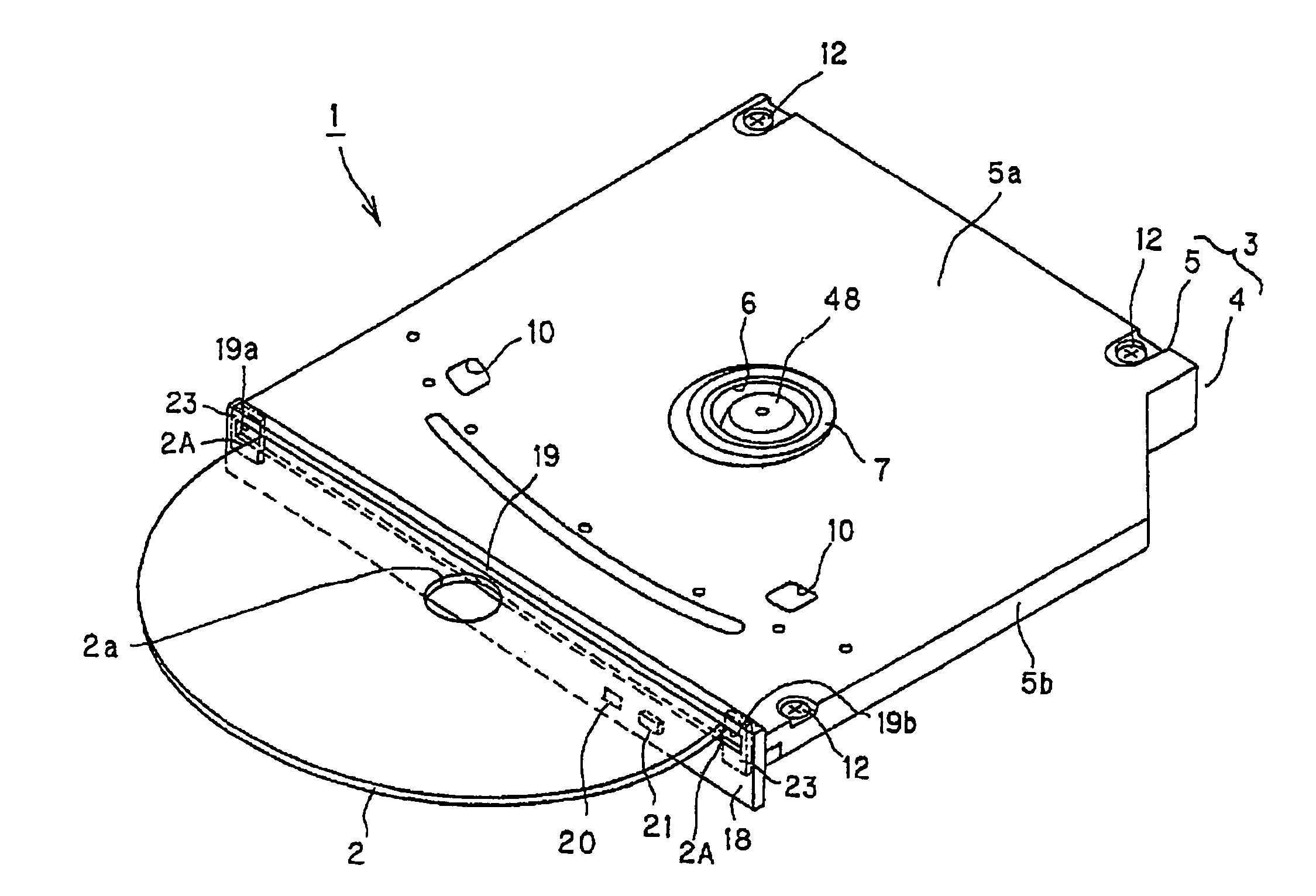
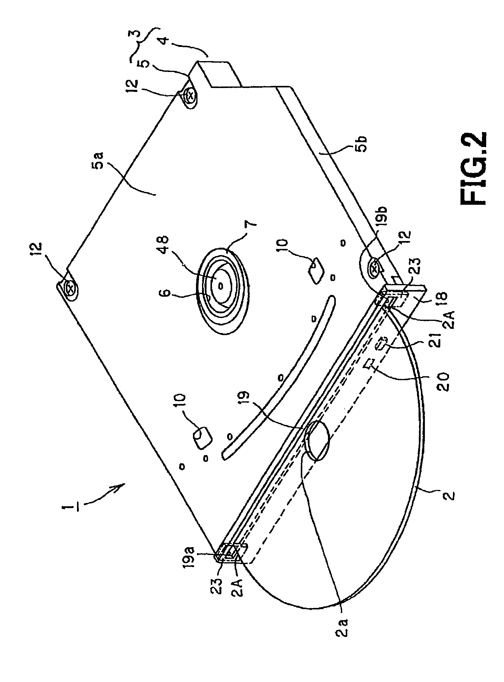
[0050]Embodiments of a disk drive apparatus according to the present invention will be described in detail with reference to the attached drawings. For example, as shown in FIG. 1, the disk drive apparatus 1 according to this embodiment is mounted within an apparatus body 1001 of a note type personal computer 1000. The disk drive apparatus 1 is caused to be of the configuration in which the slot-in system is employed to perform drive operation of an optical disk 2. As shown in FIG. 2, the disk drive apparatus 1 is caused to be of the configuration in which thin structure is realized to a degree such that the thickness of the entirety of the apparatus becomes equal to about 12.7 mm, and optical disk 2 such as CD (Compact Disc) or DVD (Digital Versatile Disc) is used as recording medium to perform recording or reproduction of information signals onto the optical disk 2.

[0051]As shown in FIG. 2, the disk drive apparatus 1 comprises a casing 3 constituting the apparatus body. The casing...


PUM

PropertyMeasurementUnit
thicknessaaaaaaaaaa
thicknessaaaaaaaaaa
diameteraaaaaaaaaa

Abstract

The present invention is directed to a disk drive apparatus in which an optical disk (2) is detachably loaded, and comprises a casing (3) including a front panel (18) in which a disk insertion / withdrawal hole (19) of which length in length direction is caused to be substantially the same as the diameter of the optical disk, and a biasing member (70) for biasing plural rotational arms (61), (62) for holding the outer circumference of the optical disk therebetween in a predetermined direction in accordance with carrying position of the optical disk, wherein, between the disk insertion / withdrawal position and the disk loading position, there are provided a disk carrying mechanism (60) for performing carrying operation of the optical disk, a disk loading portion (41) to which the optical disk is loaded, a disk rotation drive mechanism (42) for optical disk, an optical pick-up (43) for performing recording and / or reproduction of information signals with respect to the optical disk, and a pick-up feed mechanism (44) for allowing the optical pick-up to undergo feed operation, wherein a slide contact piece (23) caused to be slidably in contact with the outer circumferential surface of the optical disk caused to undergo insertion / withdrawal operation with respect to the disk insertion / withdrawal hole is provided at one end portion in a length direction of the disk insertion / withdrawal hole to limit sudden movement of the optical disk.

Description

[0001]This Application is a Continuation-in-Part and claims the benefit under 35 U.S.C. 120 of International application PCT / JP2005 / 014765, filed Aug. 11, 2005, which, in turn, claims priority of Japanese Patent Application No. 2004-235621, filed on Aug. 12, 2004 and Japanese Patent Application No. 2004-276028, filed on Sep. 22, 2004, the entireties of which are incorporated by reference herein.TECHNICAL FIELD[0002]The present invention relates to a disk drive apparatus adapted for performing recording and / or reproduction of information signals with respect to an optical disk, and more particularly relates to a disk drive apparatus adapted so that the slot-in system is employed to perform attachment / detachment of optical disk permitted to undergo attachment / detachment.BACKGROUND ART[0003]Hitherto, as recording media for information signals, there are provided optical disks such as CD (Compact Disk) or DVD (Digital Versatile Disk), and / or magneto optical disks such as MO (Magneto Opt...

Claims


Application Information

Patent Timeline
Patent Type & Authority Patents(United States)
IPC IPC(8): G11B17/04
CPCG11B17/051G11B17/04G11B33/02
Inventor OMORI, KIYOSHISUZUKI, YUJIOOTSUKA, TAKASHIJITSUKAWA, KEIJIMUTO, SATOSHINATSUBORI, KOJIAIZAWA, HIDEKUNI
Owner SONY CORP
Why Eureka
Try Eureka