Control circuit, dcdc converter, and driving method

Active Publication Date: 2012-04-05
SEMICON ENERGY LAB CO LTD
View PDF9 Cites 7 Cited by
  • Summary
  • Abstract
  • Description
  • Claims
  • Application Information

AI Technical Summary

Benefits of technology

[0033]According to the present invention, it is possible to provide a DCDC converter that achieves optimal power efficiency regardless of po

Problems solved by technology

However, with this method, the variable range of oscillation frequency cannot be widened.
If a current is to be changed largely in such a manner, the current mirror cannot operate normally since it operates outside the saturation region because of the Early effect of the transistor, for example, and an expected oscillation frequency might not be obta

Method used


Image

  • Control circuit, dcdc converter, and driving method
  • Control circuit, dcdc converter, and driving method
  • Control circuit, dcdc converter, and driving method

Examples


Example

Embodiment 1

[0049]In this embodiment, structural examples of a DCDC converter and a control circuit to which a triangle-wave generator circuit with a wide variable range of oscillation frequency is applied will be described with reference to FIG. 1, FIGS. 2A and 2B, and FIG. 3.

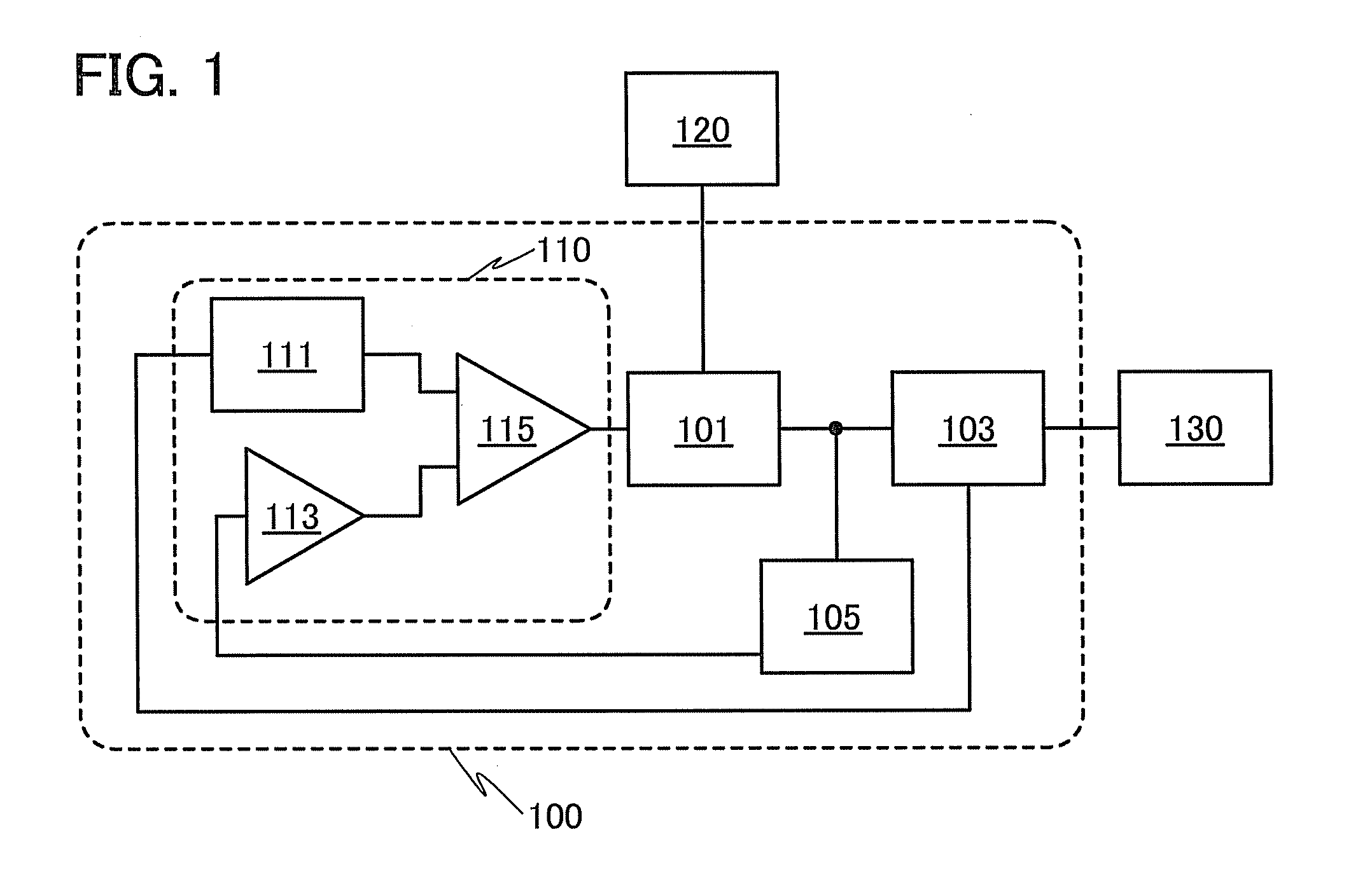
[0050]FIG. 1 is a block diagram illustrating a configuration of a DCDC converter.

[0051]A power source 120 is connected to an input side of a DCDC converter 100 exemplified in this embodiment, and a load circuit 130 is connected to an output side thereof. The DCDC converter 100 includes a control circuit 110, a power conversion circuit 101 to which an output of the control circuit 110 and the power source 120 are connected, a load current detector circuit 103 connected to an output of the power conversion circuit 101, and an output voltage detector circuit 105.

[0052]The power conversion circuit 101 outputs a stable voltage to the load circuit 130 using power input from the power source 120 and a PWM control si...

Example

Embodiment 2

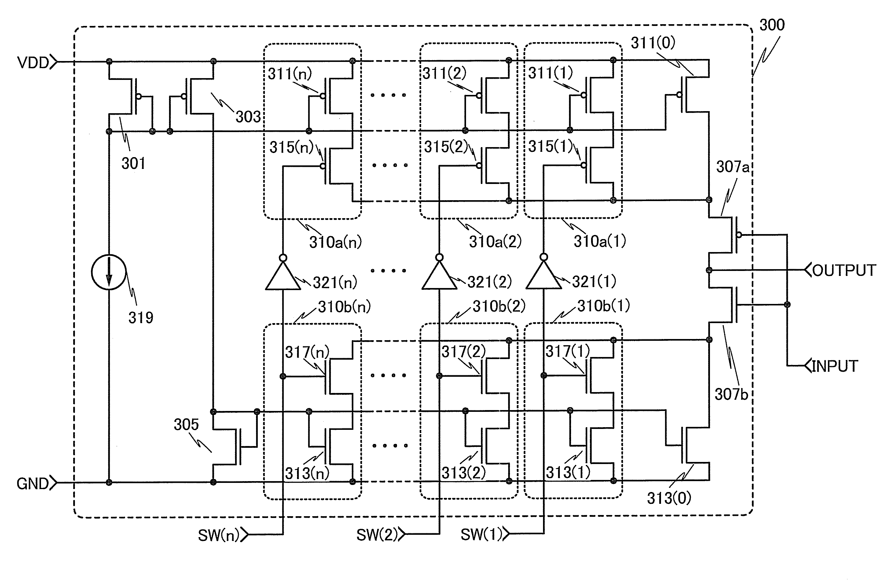
[0088]In this embodiment, a more specific example of the configuration of the current generator circuit described in Embodiment 1 will be described with reference to FIG. 4. Note that the configuration and functions described in this embodiment have a lot in common with those in Embodiment 1; therefore, the description is not repeated or is simplified for portions with the same configuration or function as Embodiment 1.

[0089]FIG. 4 is a circuit diagram illustrating a configuration of a current generator circuit 300 exemplified in this embodiment. As in the current generator circuit 200 described in Embodiment 1, a power supply line VDD, a ground potential line GND, and an input terminal INPUT are connected to the current generator circuit 300. A plurality of signal lines SW(1 to n) is supplied with a control signal from the load current detector circuit 103. From an output terminal OUTPUT, a forward or reverse current generated in the current generator circuit 300 is ou...

Example

Embodiment 3

[0106]In this embodiment, an example of the configuration of the current generator circuit which is different from that in Embodiment 2 will be described with reference to FIG. 5. Note that the configuration and functions described in this embodiment have a lot in common with those in the above embodiments; therefore, the description is not repeated or is simplified for portions with the same configuration or function as the above embodiments.

[0107]FIG. 5 is a circuit diagram illustrating a configuration of a current generator circuit 400 exemplified in this embodiment. As in the current generator circuits described in the above embodiments, a power supply line VDD, a ground potential line GND, and an input terminal INPUT are connected to the current generator circuit 400. A plurality of signal lines SW(1 to n) is supplied with a control signal from the load current detector circuit 103. From an output terminal OUTPUT, a forward or reverse current generated in the curre...


PUM


Abstract

A current generator circuit included in a triangle-wave generator circuit in a control circuit includes plural stages of current mirrors connected in parallel with each other. The plural stages of current mirrors are placed so that the sum of output currents output therefrom becomes an output current of the current generator circuit. A switching element that controls the on/off state of a current in accordance with the amount of load current of a DCDC converter is connected to each of the current mirrors.

Description

BACKGROUND OF THE INVENTION[0001]1. Field of the Invention[0002]The present invention relates to a control circuit. Further, the present invention relates to a DCDC converter controlled by the control circuit and a driving method thereof.[0003]2. Description of the Related Art[0004]PWM control is known as one of methods for controlling a DCDC converter that changes output power in accordance with the load of a circuit and outputs stable voltage.[0005]Pulse width modulation (PWM) is a modulation method of changing the duty cycle of an output pulse. For example, in the case of applying PWM to a DCDC converter, an output voltage can be close to a desired value in the following manner: the difference between an intended voltage and an output voltage that varies depending on the size of a load of a circuit connected to the output side of the DCDC converter is fed back, and the duty cycle of an output pulse is changed in accordance with the difference.[0006]As an example of a conventional...

Claims


Application Information

Patent Timeline
IPC IPC(8): G05F1/46H03K4/06
CPCH02M3/156H03K7/08H03K4/06H02M2001/0003H02M1/0003G05F1/565G05F3/26
Inventor ITO
Owner SEMICON ENERGY LAB CO LTD
Why Eureka
Try Eureka