Hydraulic Shock Absorber

a technology of shock absorber and shock absorber, which is applied in the direction of shock absorbers, mechanical equipment, transportation and packaging, etc., can solve the problem of inability to ensure a wide range of variables

Inactive Publication Date: 2007-09-13
KYB CORP
View PDF6 Cites 19 Cited by
  • Summary
  • Abstract
  • Description
  • Claims
  • Application Information

AI Technical Summary

Benefits of technology

[0006] It is an object of this invention to provide a hydraulic shock absorber ensuring a wide variable range of the damping force in the compression stroke as well as in the extension stroke.
[0007] A hydraulic shock absorber according to this invention includes: a cylinder filled with hydraulic oil; a piston disposed slidably within the cylinder, for dividing an inside of the cylinder into a first oil chamber and a second oil chamber; and a main valve composed of a spool and a disc on which the spool is seated, the main valve being provided on the piston and disposed in a main passage through which the first oil chamber and the second oil chamber communicate with each other. Further, the hydraulic shock absorber includes: an extension-side pilot chamber formed in a back face of the spool, for urging the spool in a valve-closing direction through pilot pressure introduced via a first orifice from the either oil chamber which is at high pressure in an extension stroke; a compression-side pilot chamber formed in the back face of the spool, for urging the spool in the valve-closing direction through a pilot pressure introduced via a second orifice from the either oil chamber which is at high pressure in a compression stroke; an extension-side pressure-receiving portion provided on the spool and having a smaller pressure-receiving area than the extension-side pilot chamber, for allowing pressure to be introduced into the extension-side pressure-receiving portion from an oil chamber which is at high pressure in the extension stroke and urging the spool in a valve-opening direction against the extension-side pilot pressure; a compression-side pressure-receiving portion provided on the spool and having a smaller pressure-receiving area than the compression-side pilot chamber, for allowing pressure to be introduced into the compression-side pressure-receiving portion from an oil chamber which is at high pressure in the compression stroke and urging the spool in the valve-opening direction against the compression-side pilot pressure; an extension-side poppet valve which opens when pressure in the extension-side pilot chamber reaches cracking pressure and holding the pilot pressure substantially below the cracking pressure; a compression-side poppet valve which opens when pressure in the compression-side pilot chamber reaches cracking pressure and holding the pilot pressure substantially below the cracking pressure; and a solenoid for allowing a current to flow therethrough to be excited and applying an urging force in such a direction that the solenoid reduces initial loads of springs of the extension-side poppet valve and the compression-side poppet valve.

Problems solved by technology

Consequently, there is a problem in that a wide variable range cannot be ensured.

Method used


Image

  • Hydraulic Shock Absorber
  • Hydraulic Shock Absorber
  • Hydraulic Shock Absorber

Examples


Embodiment Construction

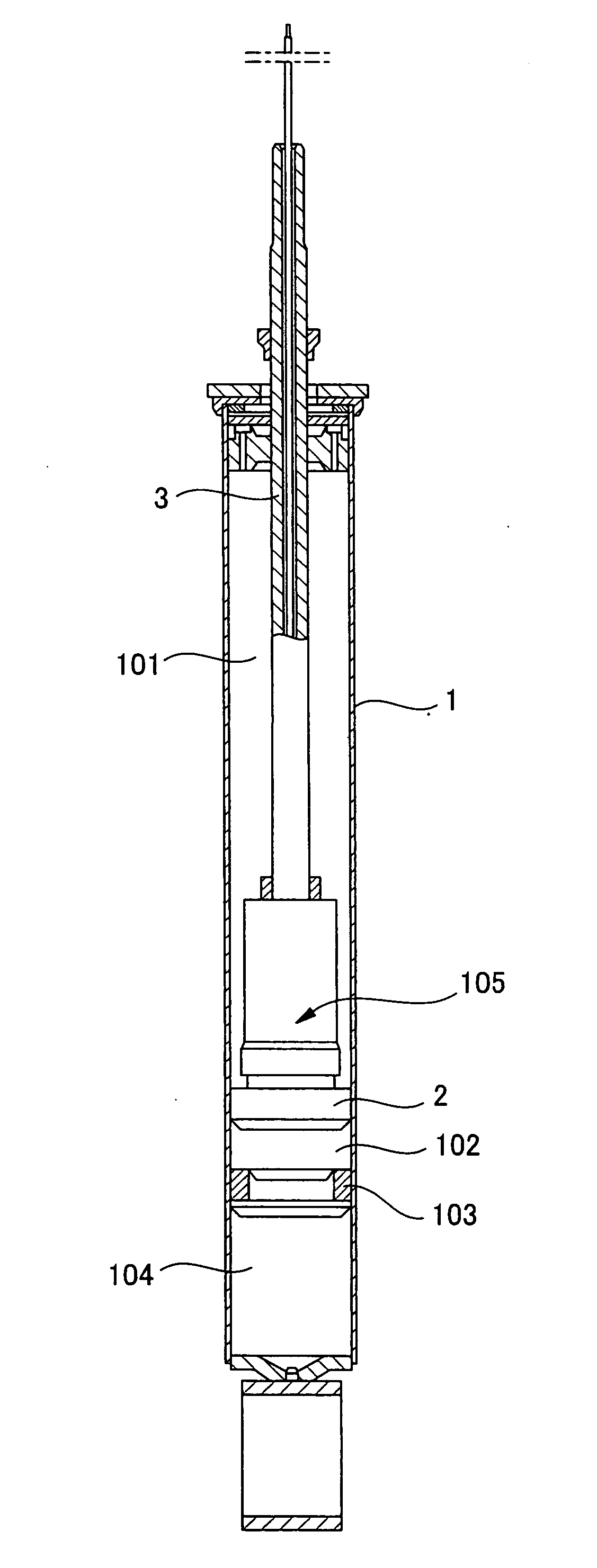
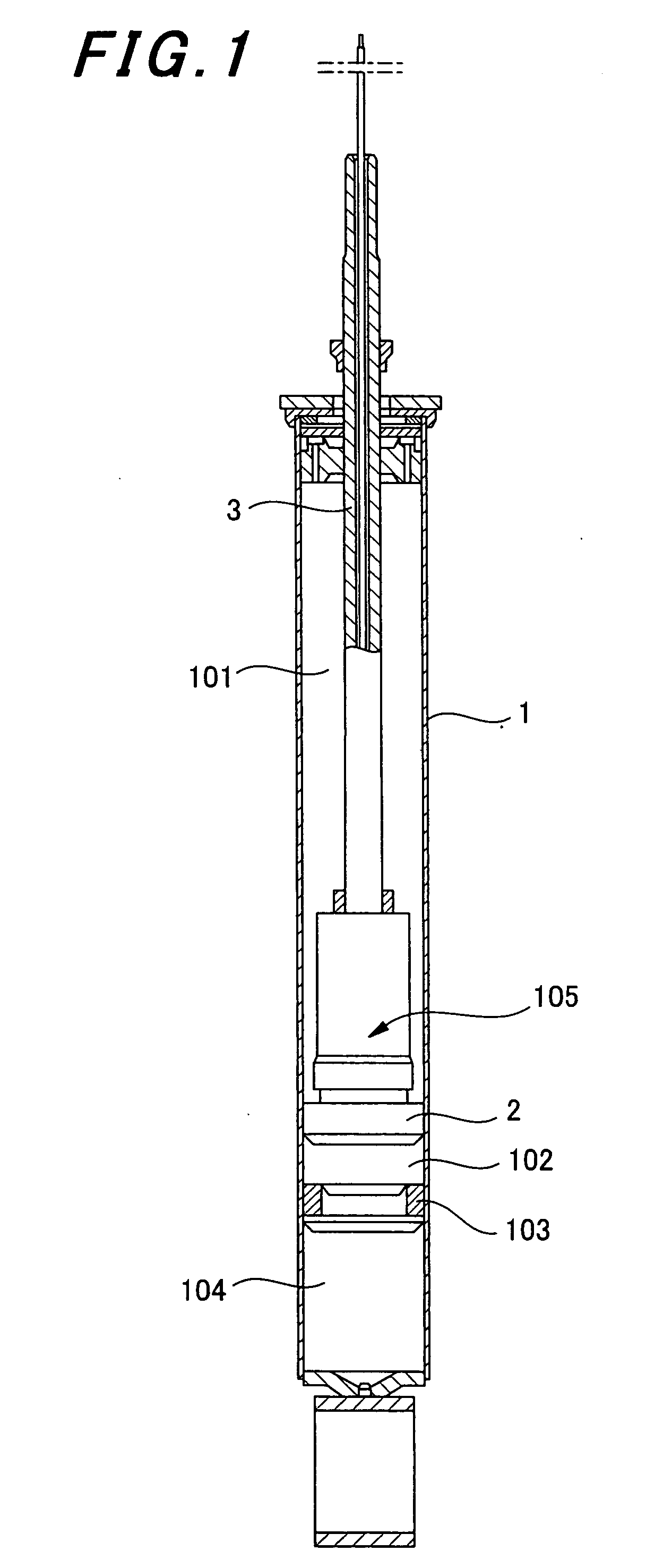
[0015] As shown in FIG. 1, a hydraulic shock absorber according to this invention is equipped with a cylinder 1, a piston 2 slidably disposed in the cylinder 1, and a piston rod 3 coupled to the piston 2.

[0016] The inside of the cylinder 1 is divided into a first oil chamber 101 and a second oil chamber 102 by the piston 2. Further, a free piston 103 is disposed in the cylinder 1, and a gas chamber 104 is thereby defined. A piston valve 105 for controlling a damping force of the hydraulic shock absorber is provided in the piston 2.

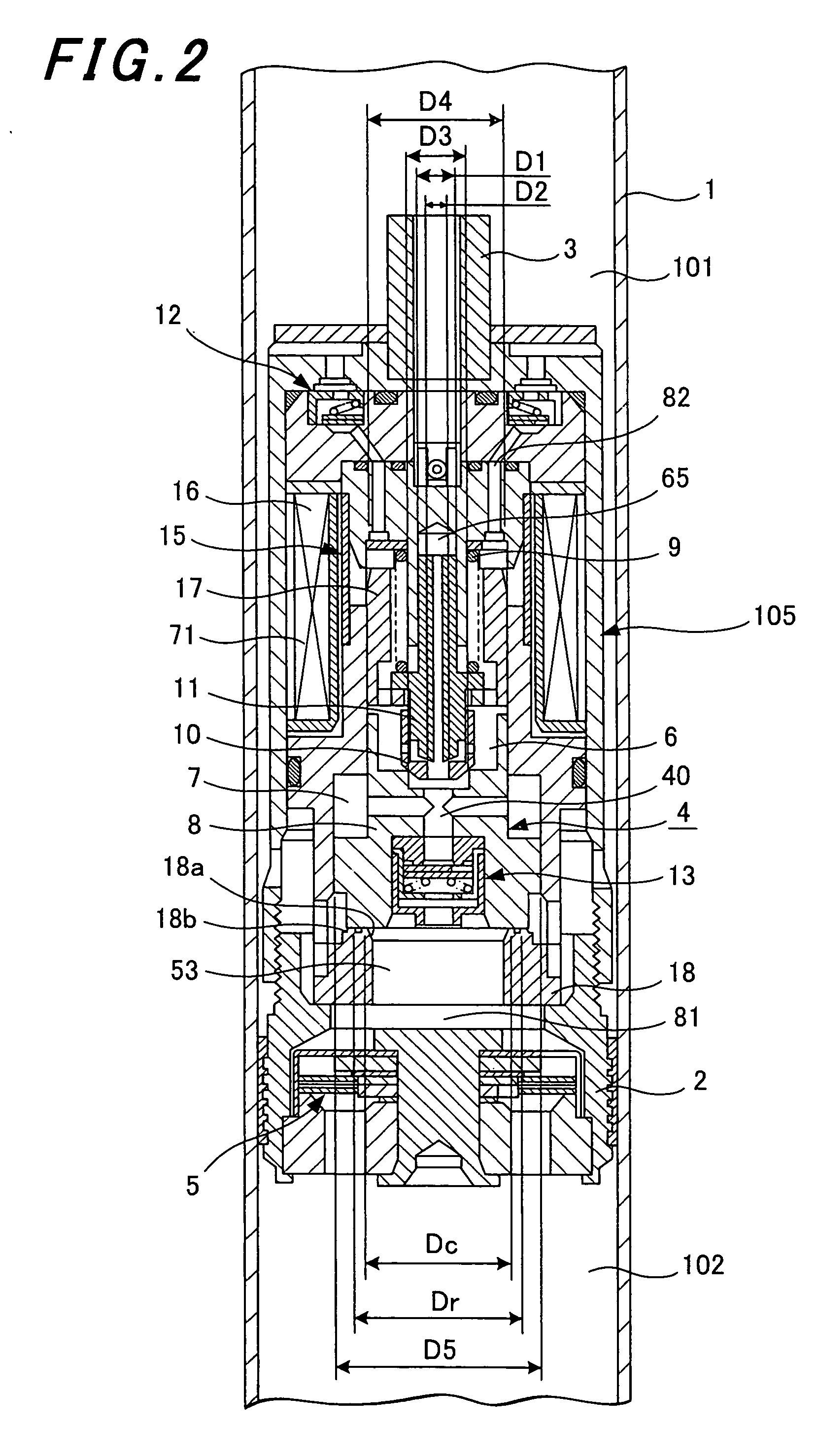
[0017]FIGS. 2 and 3 are cross-sectional views each showing the hydraulic shock absorber in a part around the piston valve 105. Although FIGS. 2 and 3 are substantially identical to each other, a dimensional relationship among respective components is described in FIG. 2.

[0018] A concrete description will be given hereinafter referring mainly to FIG. 3.

[0019] A cylindrical housing 20 is coaxially coupled to a tip of the piston rod 3. A cap 21, a guide22...


PUM


Abstract

Provided is a hydraulic shock absorber enabling an increase in a variable range of both damping forces produced in an extension stroke and a compression stroke thereof. A cylinder (1) filled with hydraulic oil is divided into first and second oil chambers (101) and (102) by a piston (2), and a main valve (4) is disposed in a main passage (81) of the piston (2). An extension side pilot chamber (6) urging a spool (8) in a valve-closing direction at pilot pressure introduced thereinto through a first orifice (32) in the extension stroke and a compression-side pilot chamber (7) urging the spool (8) in the valve-closing direction at pilot pressure introduced thereinto through a second orifice (43) in the compression stroke are formed at a back face of the spool (8) of the main valve. Also, the shock absorber comprises a pressure-receiving portion for receiving high pressure in the extension stroke and urging the spool (8) in a valve-opening direction against the pilot pressure and a pressure-receiving portion for receiving high pressure in the compression stroke and urging the spool (8) in the valve-opening direction against the pilot pressure. In addition, the shock absorber comprises an extension-side poppet valve (11) for regulating the pilot pressure in the extension stroke, a compression-side poppet valve (10) for regulating the pilot pressure in the compression stroke, and a solenoid (71) for urging to reduce initial loads of springs (9) of the extension-side and compression-side poppet valves (11) and (10) by passing current therethrough.

Description

TECHNICAL FIELD [0001] This invention relates to a hydraulic shock absorber of an adjustable damping force type, which is utilized as a suspension system for a vehicle such as an automobile. BACKGROUND ART [0002] This type of hydraulic shock absorber is disclosed in JP 11-72133 A. [0003] This hydraulic shock absorber can variably control damping forces generated in an extension stroke and a compression stroke independently of each other. [0004] In this case, while a spool for generating a damping force is urged through pilot pressure set by a poppet valve in the extension stroke, the spool is directly urged by a spring in the compression stroke. A magnetic force of a solenoid is applied in such a direction as to reduce an urging force of the spring, so the damping force can be variably controlled based on current through the solenoid. DISCLOSURE OF THE INVENTION [0005] In a conventional hydraulic shock absorber, however, the spool for changing the damping force as described above is...

Claims


Application Information

Patent Timeline
Patent Type & Authority Applications(United States)
IPC IPC(8): F16F5/00B60G17/08F16F9/348F16F9/46
CPCF16F9/465B60G17/08F16F9/32F16F9/46
Inventor MASAMURA, TATSUYA
Owner KYB CORP
Why Eureka
Try Eureka