Image processing apparatus, image processing method, inkjet printing apparatus, and inkjet printing method

a technology of image processing and inkjet printing, which is applied in the field of image processing apparatus, image processing method, inkjet printing apparatus, inkjet printing method, can solve the problems of large amount of time required for correction processing, easy density unevenness of printed images, and increase in cost, so as to reduce image deterioration and limit the increase of necessary memory and processing time

Active Publication Date: 2012-04-05
CANON KK
View PDF6 Cites 11 Cited by
  • Summary
  • Abstract
  • Description
  • Claims
  • Application Information

AI Technical Summary

Benefits of technology

[0009]An object of the invention is to enable image data correction for reducing image deterioration caused by nozzle ejection characteristic variation in an ink jet printing apparatus, while at the same time limiting the increase of necessary memory and processing time.

Problems solved by technology

Print heads that are used in inkjet type printing apparatuses have ejection amount variations among the multiple nozzles, due to manufacturing errors, etc.
When there is ejection amount variation such as this it is easy for density unevenness to occur in printed images.
H10-13674 (1998) are applied to a long print head having many nozzles, because image data processing is carried out at each nozzle, a problem arises wherein a large amount of time is necessary for correction processing.
There is also a problem wherein a large amount of memory capacity becomes necessary when correcting images using head shading technique, which brings about an increase in cost.
Furthermore, when the resolution of the nozzles of the print head are made high, it is also required that the resolution of the detection device that detects the ejection amount of each nozzle must also be high, which also causes an increase in apparatus cost.

Method used


Image

  • Image processing apparatus, image processing method, inkjet printing apparatus, and inkjet printing method
  • Image processing apparatus, image processing method, inkjet printing apparatus, and inkjet printing method
  • Image processing apparatus, image processing method, inkjet printing apparatus, and inkjet printing method

Examples


first embodiment

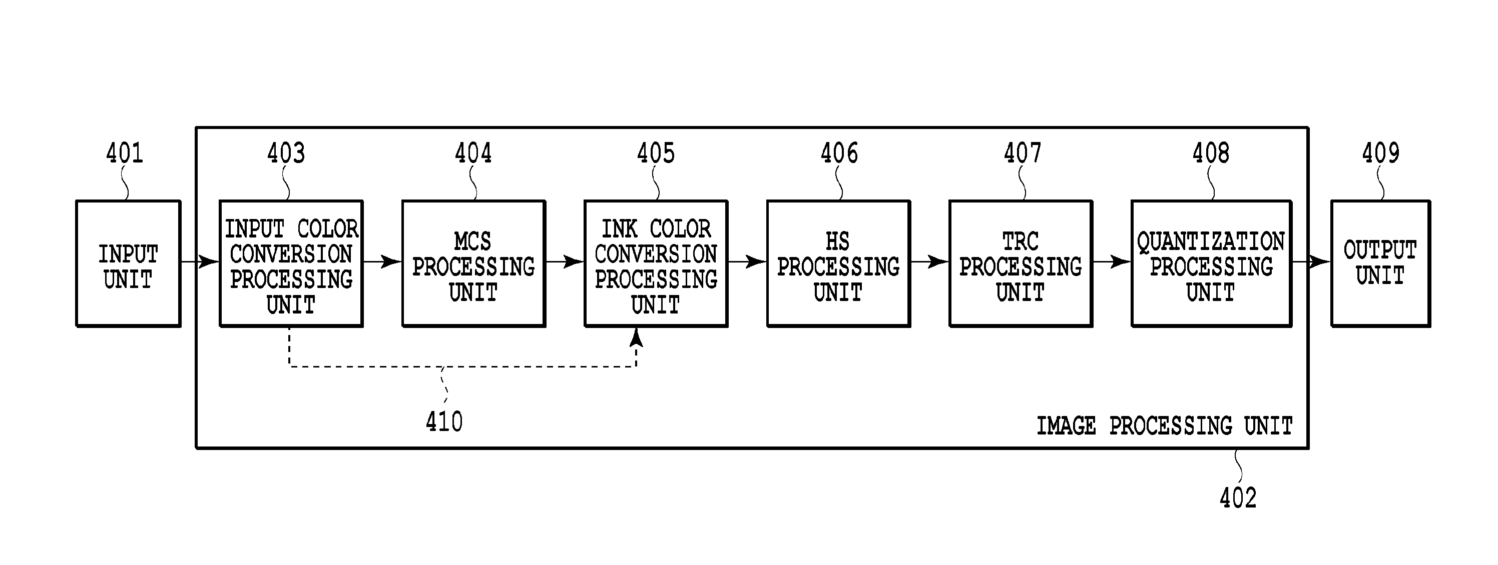
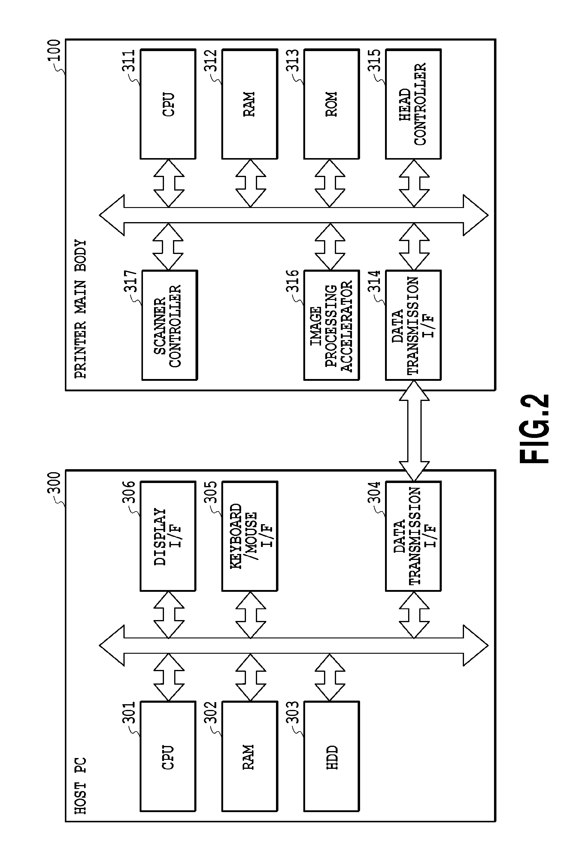
[0035]FIG. 3 is a block diagram illustrating the configuration of an image processing unit of an inkjet printer of a first embodiment of the invention. In this embodiment, the respective components for the control and processes of the printer 100 illustrated at FIG. 2 constitute the image processing unit. Note that the applicability of the invention is not limited to this configuration. As examples, the image processing unit may be arranged in the PC 300 shown at FIG. 2, or part of the image processing unit may be arranged in the PC 300 while the remainder is arranged in the printer 100.

[0036]As shown at FIG. 3, an input unit 401 outputs image data received from the host PC 300 to the image processing unit 402. The image processing unit 402 is configured to have an input color conversion processing unit 403, a MCS processing unit 404, an ink color conversion processing unit 405, an HS processing unit 406, a TRC processing unit 407, and a quantization processing unit 408.

[0037]At the...

second embodiment

[0066]A second embodiment of the invention will be explained next.

[0067]FIG. 11 is diagram that illustrates print heads 501 to 504, which are used in the second embodiment and which differ in the following respects from the print heads used in the above described first embodiment illustrated at FIGS. 4A and 4B. That is, the print heads used in the above described first embodiment are configured such that the overlap portions of the print heads of each color overlap in the conveyance direction of the print medium (Y direction) (they are present at the same position along the nozzle alignment direction (x direction)). In contrast, the print heads of the second embodiment have a configuration wherein, as shown at FIG. 11, the overlap portions of the print heads of each color, K_T, C_T, M_T, and Y_T, are arranged such that they do not overlap in the conveyance direction of the print medium (y direction).

[0068]Now, at each of the print heads shown at FIG. 11, nozzle resolution is 1200 dp...

third embodiment

[0075]A third embodiment of the invention will be explained next.

[0076]At the above described first and second embodiments examples were explained wherein one processing block was established with respect to the HS processing and the MCS processing of the image data corresponding to the nozzles of the print head. In contrast, in the third embodiment a plurality of differing processing blocks are established as the processing blocks of the image data corresponding to the nozzles of the print head.

[0077]Here, the print heads of each color shown at FIG. 4A are designed to be a structure in which the nozzle count of each chip is 512 and the nozzle counts at the overlap portions are 128. In the third embodiment, with respect to the overlap portions, HS processing and MCS processing are executed at 8 nozzle intervals, which is a divisor of its nozzle count of 128. And, with respect to the non-overlap portions, 16 nozzles are set as the nozzle region, which 16 nozzles are a common divisor ...


PUM


Abstract

The invention decreases the enlargement of memory and processing time for the correction of image data carried out to reduce image deterioration caused by nozzle ejection characteristic variation in an inkjet printing apparatus. Print heads are provided with pluralities of chips that have nozzle arrays formed from a plurality of nozzles. Coupled portions and non-overlap portions are formed on each chip. An image processing apparatus sets input image data, which correspond to nozzle regions that are defined in nozzle arrays along the alignment direction of the nozzles of the print head and that are composed of a plurality of nozzles, as processing blocks. The input image data is processed according to parameters defined for each of those processing blocks. The boundaries of the nozzle regions corresponding to the input image data of the processing blocks are established according to the boundaries of the overlap portions and the non-overlap portions.

Description

BACKGROUND OF THE INVENTION[0001]1. Field of the Invention[0002]The invention relates to inkjet printing apparatuses that print images using print heads on which pluralities of chips provided with multiple ink ejecting nozzles are aligned along the alignment direction of the nozzles, and to image processing apparatuses, etc., that process data used thereby.[0003]2. Description of the Related Art[0004]As for inkjet printing apparatuses, print heads are used that have ejection portions (hereafter these ejection portions will also be referred to as nozzles) that are aligned in a constant direction and that are composed of inkjet printing elements, ejection ports, and liquid paths in communication therewith. As for inkjet printing apparatuses, so-called full-line type inkjet printing apparatuses are known, which perform printing operations by way of fixing the print heads with respect to the main body of the printing apparatus and conveying the print medium in a direction that crosses t...

Claims


Application Information

Patent Timeline
Patent Type & Authority Applications(United States)
IPC IPC(8): B41J29/38
CPCB41J2/2146G06K2215/111G06K15/102B41J2/145B41J2/175
Inventor GOTO, FUMITAKAMIYAKE, NOBUTAKAIKEDA, TOHRUYAMADA, AKITOSHIONO, MITSUHIROIGUCHI, RYOSUKEKAGAWA, HIDETSUGUISHIKAWA, TOMOKAZUNAKAGAWA, JUNICHI
Owner CANON KK
Why Eureka
Try Eureka