Object information acquiring apparatus and control method for same

a technology of object information and control method, which is applied in the field of object information acquisition apparatus and control method for same, can solve problems such as image deterioration, and achieve the effect of reducing image deterioration

Inactive Publication Date: 2014-04-10
CANON KK
View PDF1 Cites 23 Cited by
  • Summary
  • Abstract
  • Description
  • Claims
  • Application Information

AI Technical Summary

Benefits of technology

[0026]According to the present invention, it is possible to provide an object information acquiring apparatus which can reduce image deterioration caused by the effects of detecting reflected waves.

Problems solved by technology

If an optical characteristics distribution is created using a detection signal which includes a reflected wave, then there is a problem in that an artifact due to the reflected wave is produced and image deterioration occurs.

Method used


Image

  • Object information acquiring apparatus and control method for same
  • Object information acquiring apparatus and control method for same
  • Object information acquiring apparatus and control method for same

Examples


first embodiment

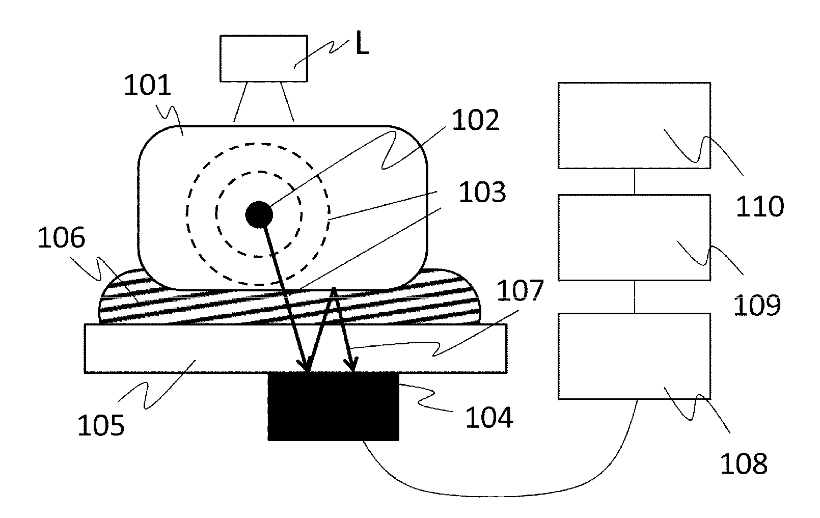
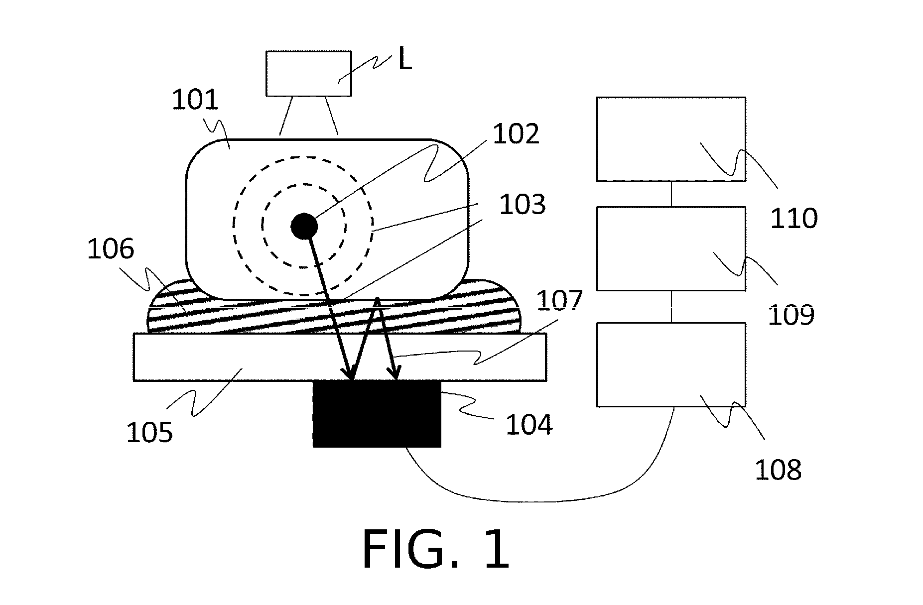
[0097]One example of a photoacoustic image-forming apparatus to which the present invention is applied will now be described. The apparatus used in shown in FIG. 1.

[0098]In the present embodiment, a YAG laser-pumped Ti:Sa laser system was used as the light source L. With this laser system, it is possible to irradiate light having a wavelength of 700 to 900 nm onto the object. The irradiation surface area of the laser light is enlarged by using an optical system, such as a mirror and a beam expander, and is then irradiated onto the object. The probe 104 employed was a probe with a two-dimensional configuration of 20 by 30 elements having an element width of 1 mm. In the front-stage processing unit 108, a 600 ch signal is received simultaneously from the probe, and subjected to amplification processing and digital conversion processing. The signal processing unit 109 processes this digital signal.

[0099]A human gastrocnemius muscle was measured as the object 101. A flat plate made from...

second embodiment

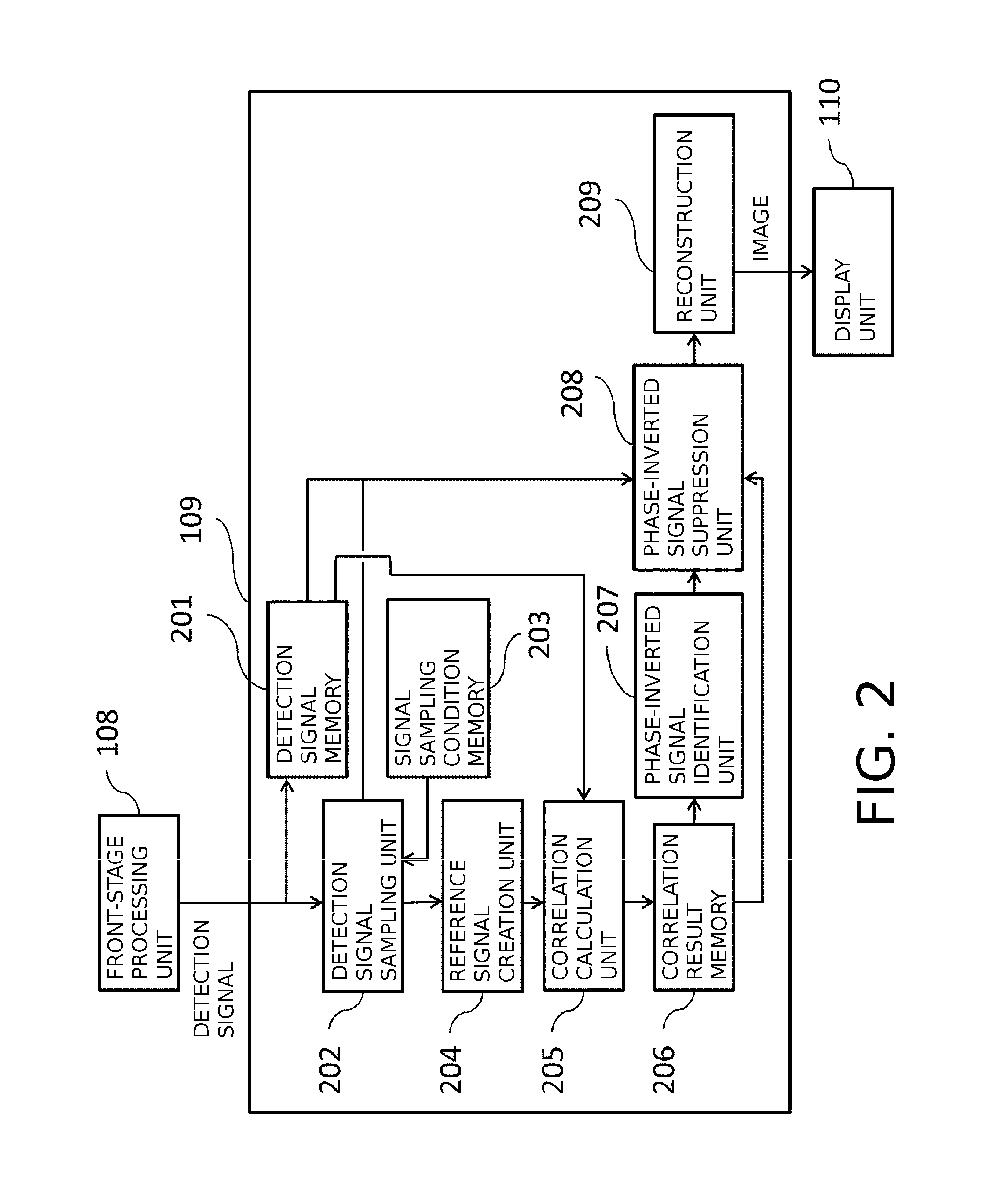
[0106]The basic composition of the apparatus according to this embodiment is the same as that of the first embodiment. However, the processing of the signal processing unit 109 is different to that of the first embodiment. In the first embodiment, the reference signal was created simply by averaging the sampling signal, but in the present embodiment, a reference signal was created by attenuating the frequency component through applying a filter to the averaged sampling signal.

[0107]The intensity of each frequency of the signal changes in direct proportion to exp (−ax). Here, a is the attenuation coefficient and x is the distance through which the signal has propagated. Therefore, the frequency intensity of the phase-inverted signal which is received by the probe after the sampling signal has been reflected and has propagated by an excess distance of δx is attenuated by exp (−aδx) with respect to the sampling data. This attenuated light is used as a filter and is multiplied by the sa...

third embodiment

[0110]The basic composition of the apparatus according to this embodiment is the same as that of the first and second embodiments. In order to suppress the reflected signal of the photoacoustic signal generated by the object under investigation in the detection signal as disclosed in the present invention, it is necessary to extract the photoacoustic wave generated by the absorbing body under investigation, as a sampling signal. However, the detection signal also includes many waveforms other than that of the absorbing body under investigation. Therefore, in the present embodiment, in order to accurately sample the signal from the absorbing body under investigation in the detection signal, a signal waveform is added as a sampling condition.

[0111]The waveform which is added as a sampling condition uses a probe response waveform. The probe response is also called the impulse response, and is the waveform output by the probe when one pulse signal is input. A waveform which is similar t...


PUM


Abstract

An object information acquiring apparatus, including: a probe converting an acoustic wave generated from an object irradiated with light into a detection signal; and a signal processing unit generating information about the object from the detection signal, wherein the signal processing unit: extracts a sampling signal on the basis of conditions relating to the signal shape; generates a reference signal from the sampling signal; detects a phase-inverted signal, which is a portion of the detection signal where the phase is inverted with respect to the reference signal, by carrying out a correlation calculation; generates a signal after suppression by suppressing the intensity of the phase-inverted signal from the detection signal; and generates information about the interior of the object using the signal after suppression.

Description

BACKGROUND OF THE INVENTION[0001]1. Field of the Invention[0002]The present invention relates to an object information acquiring apparatus and a control method for same.[0003]2. Description of the Related Art[0004]In the field of medicine, there has been active research into optical imaging apparatuses which irradiate light onto an object under inspection, such as a living organism, from a light source, such as a laser, and create an image of information on the interior of the object obtained on the basis of the incident light. One example of optical imaging technology of this kind is photoacoustic imaging (PAI). In photoacoustic imaging, pulsed light generated by a light source is irradiated onto an object, an acoustic wave (typically, an ultrasonic wave) generated by the tissue of the object that has absorbed the energy of the pulsed light which has propagated and diffused inside the object is detected, and object information is imaged (formed into an image) on the basis of this d...

Claims


Application Information

Patent Timeline
Patent Type & Authority Applications(United States)
IPC IPC(8): A61B5/00
CPCA61B5/7246A61B5/0095
Inventor WADA, YOSHIKO
Owner CANON KK
Why Eureka
Try Eureka