Image converter circuit

a converter circuit and image technology, applied in the field of image converter circuits, can solve the problems of unsuitable boundary between the blocks, unnatural moving, and large change of magnification between the blocks, and achieve the effect of reducing image deterioration in the panoramic display

Active Publication Date: 2007-05-03
LAPIS SEMICON CO LTD
View PDF6 Cites 9 Cited by
  • Summary
  • Abstract
  • Description
  • Claims
  • Application Information

AI Technical Summary

Benefits of technology

[0027] According to the present invention, the image divider vertically divides the enlarged image into a plurality of areas so as to regulate the numbers of pixels of the respective areas to be nearly the same value. Then, the enlargement magnifications corresponding to the respective areas are set to be values that, in accordance with a monotonic increasing function (e.g., a quadratic function), increases with increasing distance from a center area of the areas and has a minimal value at the center area. This makes it possible to calculate magnification-designating information that causes the size of an input image to be converted into the size of the enlarged image, regardless of the size of the enlarged image. Further, the magnification-designating information allows for smooth change depending on the distance from the center area. Therefore, there can be an effect of reducing image deterioration in panoramic display.

Problems solved by technology

However, the conventional image converter circuit involves the following problem.
Therefore, the enlarged image cannot be appropriately displayed.
Furthermore, in the panoramic display, because of incapability of providing the large number of the blocks into which the screen can be divided, there encounters a great change of the magnification between the blocks.
With displaying such a moving image that moves horizontally, there is a problem in that the moving looks unnatural and unsuitable at the boundary between the blocks.

Method used


Image

  • Image converter circuit
  • Image converter circuit
  • Image converter circuit

Examples


Embodiment Construction

[0032] This application is based on Japanese Patent Application No. 2005-313026 which is incorporated herein by reference.

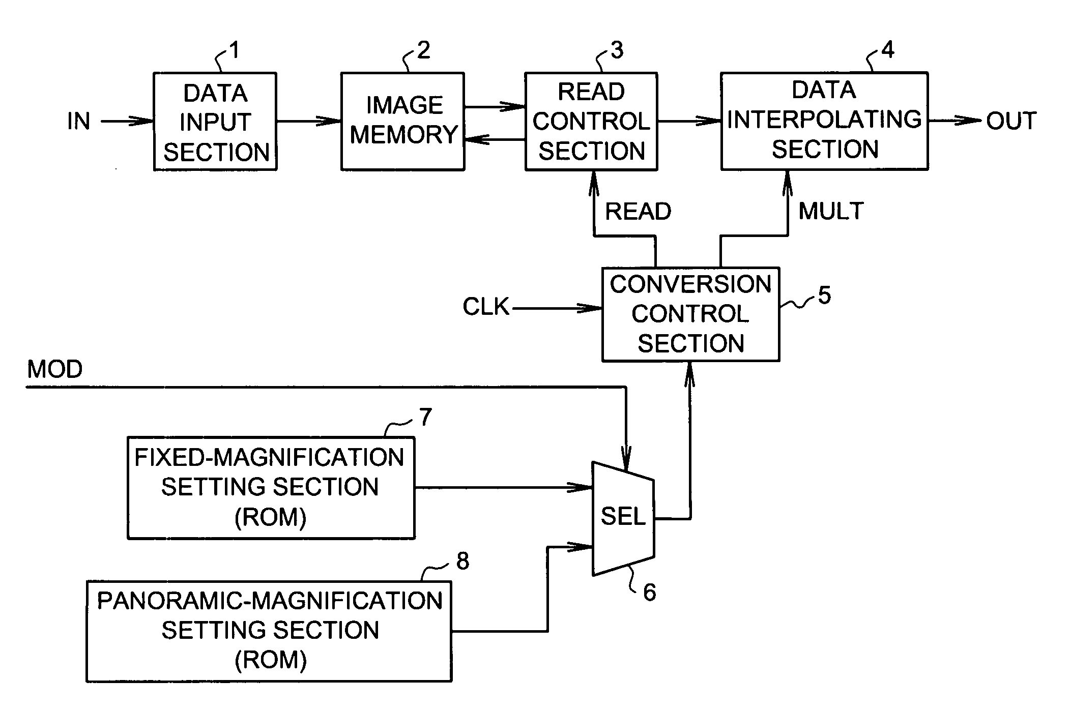
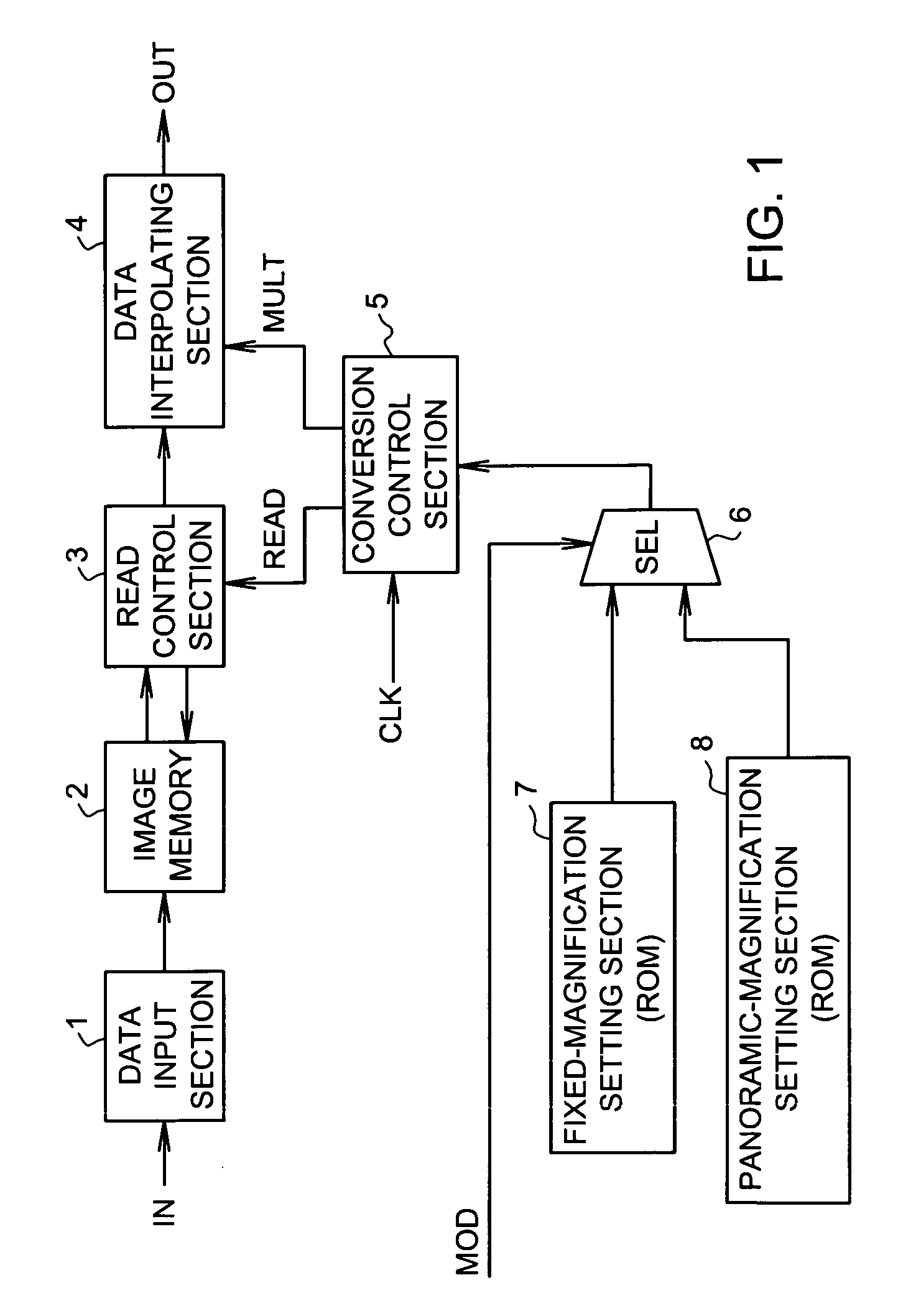
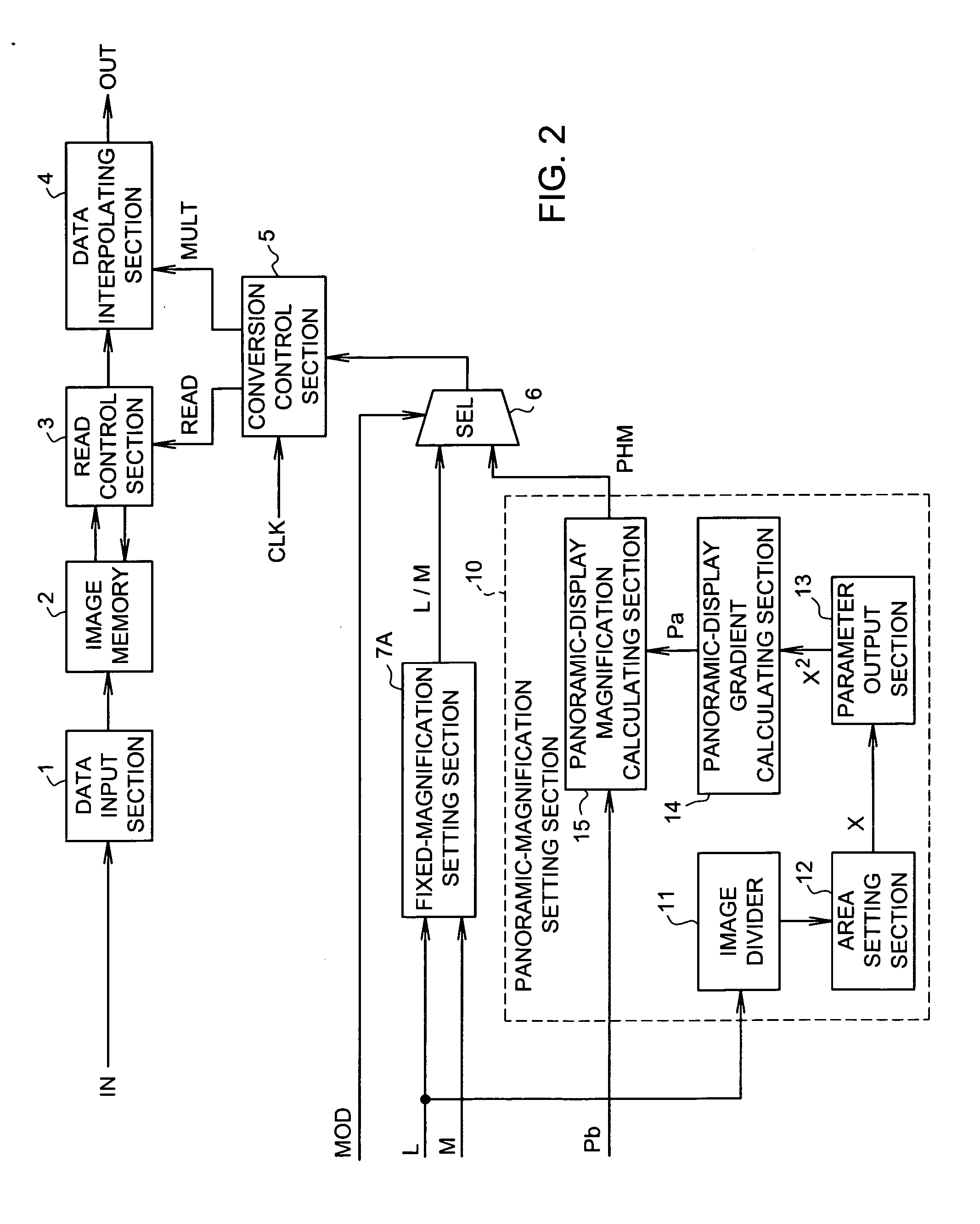
[0033]FIG. 2 is a configuration diagram of an image converter circuit illustrating an embodiment according to the present invention. Like reference numerals designate corresponding similar elements through FIGS. 1 and 2.

[0034] The image converter circuit converts the number of pixels making up one screen to output enlarged-image data OUT, in order to display the input-image data IN representing M horizontal pixels×N vertical pixels on a display device having L horizontal pixels×N vertical pixels. This circuit includes a data-input section 1 to which the input-image data IN is provided. An image memory 2 is connected to the data-input section 1. The image memory 2 is configured by N line memories, each of which stores image data representing M pixels for each of N horizontal lines. The input image data IN inputted through the data input section 1 is sequentially...


PUM


Abstract

Disclosed is an image converter circuit which is capable of being to be applied to a display device having an arbitrary number of pixels, and is capable of reducing image deterioration in panoramic display. The image converter circuit comprises: a read-control section that reads image data from an image memory in accordance with read-designating information; a data interpolating section that interpolates pixels using the image data read out from the image memory, depending upon magnification-designating information, and outputs enlarged and interpolated data; and a magnification setting section that generates the read-designating information and the corresponding magnification-designating information. The magnification setting section vertically divides the image data into a plurality of areas such that a difference in a number of pixels between the areas is within a predetermined range.

Description

BACKGROUND OF THE INVENTION [0001] 1. Field of the Invention [0002] The present invention relates to an image converter circuit for converting the horizontal / vertical number of pixels of an input image into the number of pixels of a display device, and more particularly to an image converter circuit for panoramically displaying, without image deterioration, the input-image data having a small aspect ratio (e.g., 4:3) on a display device having a larger aspect ratio (e.g., 16:9). [0003] 2. Description of the Related Art [0004]FIG. 1 is a configuration diagram of a conventional image converter circuit. The conventional image converter circuit has a data input section 1 to which is provided input-image data IN having an aspect ratio of 4:3, e.g., 720 horizontal pixels×540 vertical pixels, and has an image memory 2 connected to the data input section 1. The image memory 2 is constituted by 540 line memories for storing 720 pixels of image data of each of 540 horizontal lines. The input-...

Claims


Application Information

Patent Timeline
Patent Type & Authority Applications(United States)
IPC IPC(8): G06K9/32G09G5/00
CPCG09G5/005G09G2340/04G09G2340/0442G09G2360/02H04N5/2628H04N7/0122H04N7/01G09G3/20
Inventor YAMAMOTO, TOYOAKI
Owner LAPIS SEMICON CO LTD
Why Eureka
Try Eureka