Double Offset Surgical Tool Handle Assembly To Provide Greater Offset From The Coronal Plane

a surgical tool and handle technology, applied in the field of surgical tools, can solve the problems of increasing the risk of disease transmission from patient to patient, difficult to use current solutions without subjecting patients, and difficult to clean with relative ease complicated surgical tool handles, etc., to facilitate sterilization, prevent the separation of component parts, and facilitate sterilization

Active Publication Date: 2012-04-05
VIANT AS&O HLDG LLC
View PDF2 Cites 25 Cited by
  • Summary
  • Abstract
  • Description
  • Claims
  • Application Information

AI Technical Summary

Benefits of technology

This patent describes a special surgical tool that helps with replacing damaged hips with new ones. It's designed to be easy to clean because it can partially break down without losing its shape or function.

Problems solved by technology

The technical problem addressed in this patent text relates to improving the design of surgical tools to make them easier to clean, adjust, and manage during medical procedures. Current complicated tool handles can harbor harmful microorganisms such as prions, leading to increased risks of disease transmission between patients. Moreover, existing solution designs cause damage or pain while being inserted and extracted repeatedly during surgery. There also exists difficulty in ensuring proper placement of a prosthetic implant due to challenges in accessing the treatment site. Therefore, there is a need for an improved surgical tool handle designed to address these issues.

Method used


Image

  • Double Offset Surgical Tool Handle Assembly To Provide Greater Offset From The Coronal Plane
  • Double Offset Surgical Tool Handle Assembly To Provide Greater Offset From The Coronal Plane
  • Double Offset Surgical Tool Handle Assembly To Provide Greater Offset From The Coronal Plane

Examples


Embodiment Construction

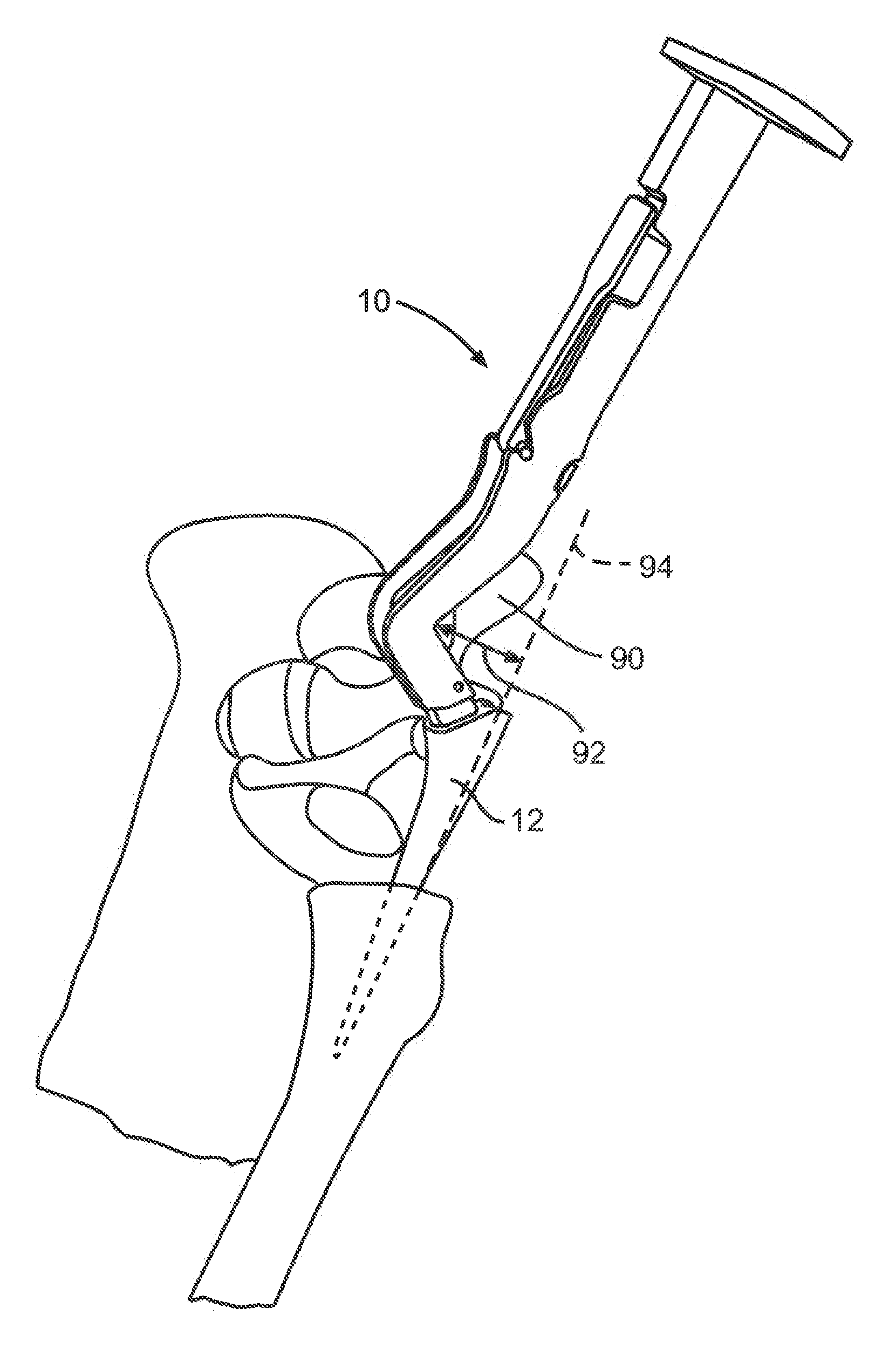
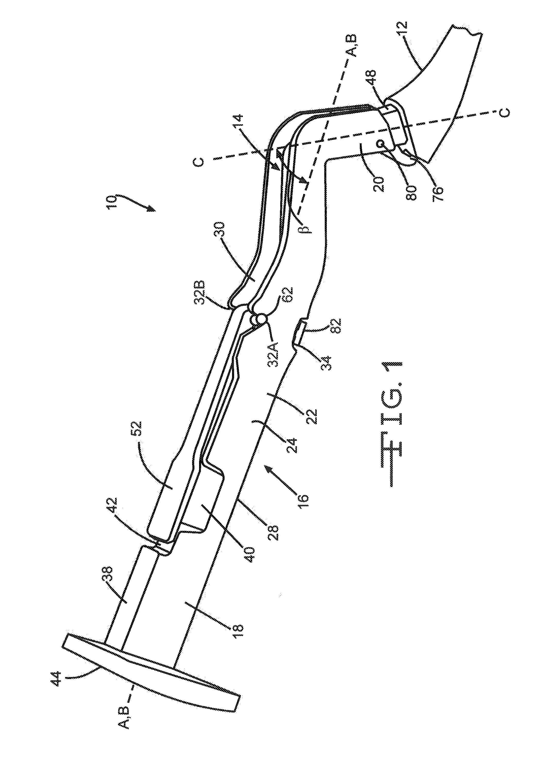
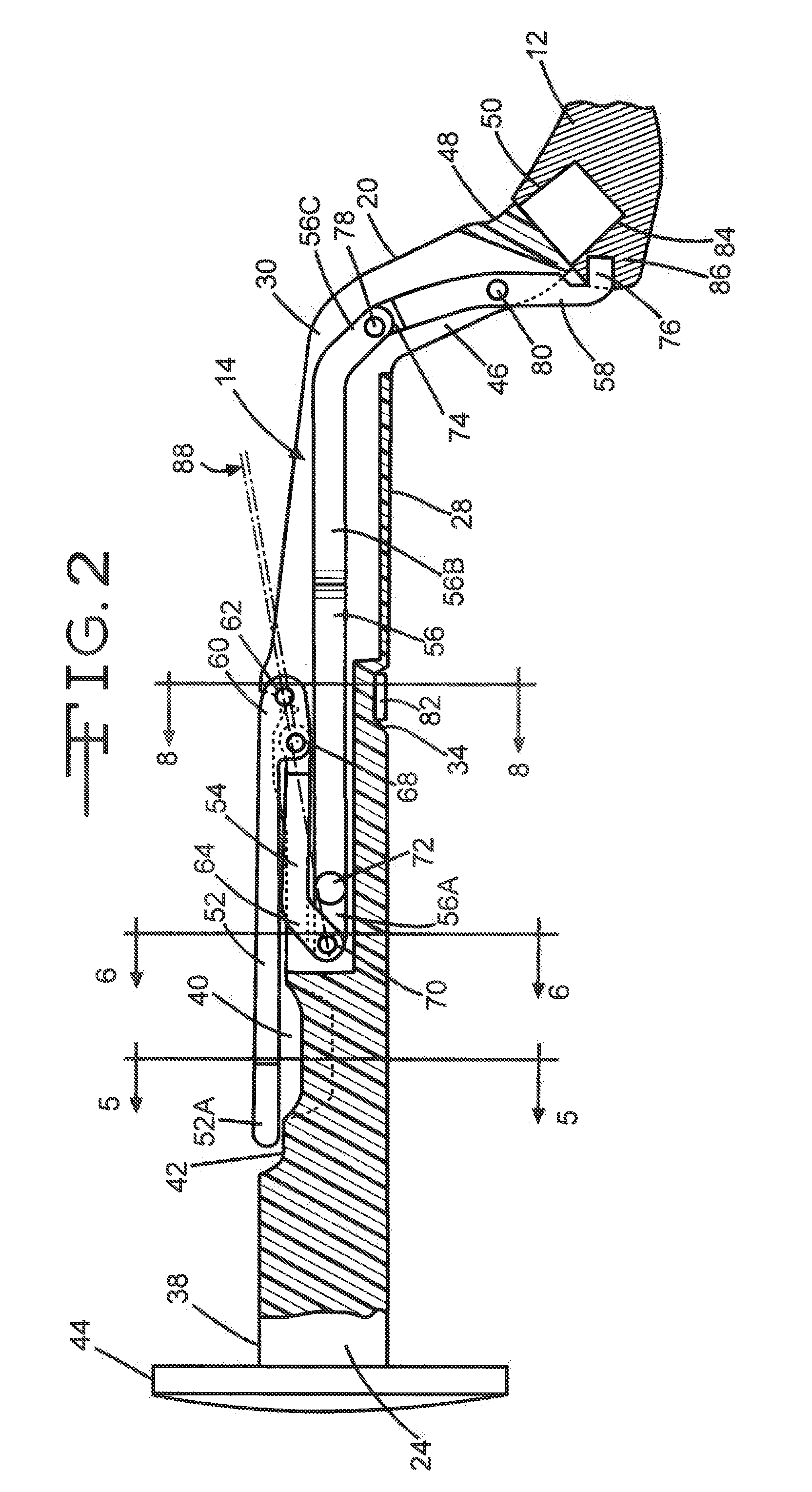
[0021]Turning now to the drawings, FIGS. 1 to 4 and 7 illustrate a surgical handle assembly 10 according to the present invention. The handle assembly 10 is shown connected to a surgical tool, such as a broach or rasp 12 for performing a minimally invasive hip replacement surgery. Other tools useful with the handle assembly 10 include, but are not limited to, reamers, angled drivers, twist drills, flexible drills, cannulated drills, bayonet drills, bayonet taps, drill guides, adjustable angle drill guides, taps, and cannulated taps.

[0022]The handle assembly 10 generally comprises a linkage train 14 disposed within a housing 16. The housing 16 had a length that extends from a proximal housing section 18 to a distal neck section 20 with an intermediate housing section 22 there between. The intermediate housing section 22 comprises spaced apart right and left side walls 24 and 26 extending upwardly from a bottom wall 28 to an upper opening 30.

[0023]A unique feature of the present handl...


PUM


Abstract

A surgical tool handle for releasable connection to a surgical tool is described. The tool handle comprises a housing providing a linkage chamber extending from a proximal housing grip end to a distal housing tool end for receiving a tool. A tool linkage is partially housed within the linkage chamber. That way, manipulation of the tool linkage causes a locking pawl to pivot with respect to the housing from an open configuration ready to receive a tool for attachment to the housing to a closed configuration engageable with the tool supported at the distal housing tool end.

Description


Claims


Application Information

Patent Timeline
Owner VIANT AS&O HLDG LLC
Why Eureka
Try Eureka