Surgical device

Inactive Publication Date: 2006-10-26
BIOMET UK
View PDF12 Cites 16 Cited by
  • Summary
  • Abstract
  • Description
  • Claims
  • Application Information

AI Technical Summary

Benefits of technology

[0011] The second formation may be integrally formed with the second portion. It is particularly advantageous to form the first formation integrally with the first portion and/or the second formation with the second portion, because the less components there are in a su

Problems solved by technology

This will increase or decrease femoral offset and thus alter tissue tension, stability, but at the same time will also affect leg length.
Such an arrangement provides good lateral alignment, but may not prevent displacement o

Method used


Image

  • Surgical device
  • Surgical device

Examples


Embodiment Construction

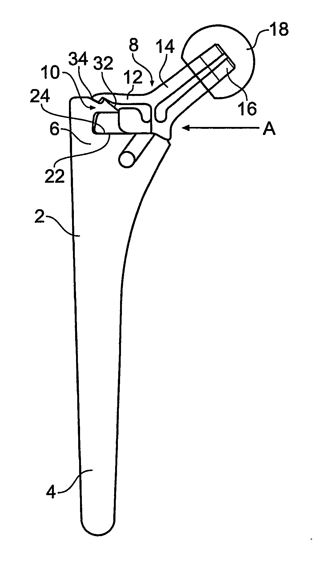
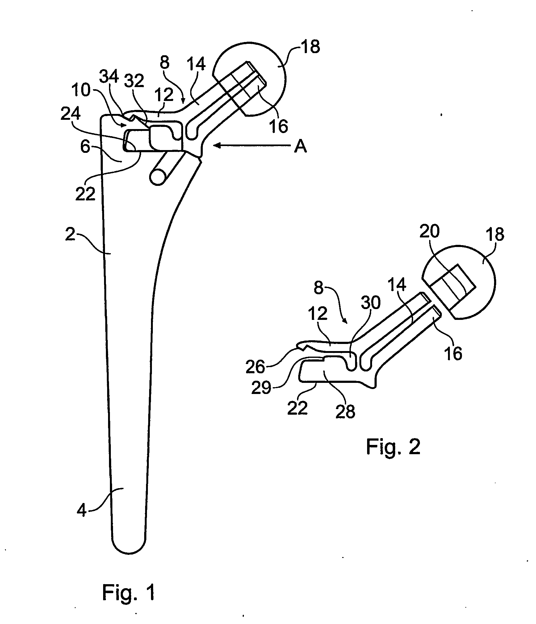
[0026] The following description of the embodiment(s) is merely exemplary in nature and is in no way intended to limit the invention, its application, or uses. Moreover, while the description below is directed to a hip prosthesis, the same may be directed to an implant for any portion of the body.

[0027]FIGS. 1 and 2 illustrate an exemplary surgical device comprising a femoral broach or file 2 comprising a file portion or stem 4 which tapers outwardly towards an enlarged fixing portion 6. An adaptor 8 may be connected to the fixing portion 6 by cooperating formations 10, 12. The adaptor 8 may be provided with a shaft 14 which tapers towards a free end 16 of the adaptor 8. A trial femoral head 18, having a socket 20 which tapers inwardly towards its base, may be received closely on the shaft 14.

[0028] A planar guide surface 22 may be formed on the adaptor 8 and rests on a corresponding planar guide surface 24 formed on the fixing portion 6 of the femoral file 2.

[0029] The second fo...


PUM


Abstract

A surgical device includes a first portion and a second portion. The first and second portions are releasably connected together by cooperating first and second formations. The first formation may be formed on the first portion. The second formation includes a resilient arm which is formed on the second portion and engages the first formation on the first portion. The resilient arm may be integrally formed with the second portion.

Description

FIELD [0001] This invention relates to a surgical device and particularly relates to a device having two main components which are interconnected by a “snap-fit” connection. INTRODUCTION [0002] One goal of hip reconstruction is to attempt to reproduce the normal kinematics of the hip by recreating the functional geometry of the acetabulum and proximal femur. This can greatly influence the outcome of the operation, restoring normal muscle function, gait and ultimately the longevity of the implant. [0003] In one exemplary replacement hip surgery a femoral component is inserted into a prepared femur. The femoral component may have a stem portion which projects into the femoral canal of the prepared femur and may have an integral or separate modular head of substantially spherical shape. The ball-like head of the femoral component may be received within an acetabular cup component which is implanted in the patient's hip socket, i.e., the acetabulum. The acetabular cup may have a substan...

Claims


Application Information

Patent Timeline
IPC IPC(8): A61B17/00A61B17/16A61F2/36A61F2/46
CPCA61B17/162A61B17/1659A61B17/1668A61B2017/0046Y10T403/53A61F2002/3611A61F2002/3625A61F2002/365A61F2002/3652A61F2/4684A61F2/36A61F2/46F16B2/20
Inventor METCALFE, NICK JAMES THEOPHILUSBIGSBY, ROBERT JOHN ANDREW
Owner BIOMET UK
Why Eureka
Try Eureka