

Fiber Project Evaluation Tool and Related Methods, Graphical User Interfaces, and Computer-Readable Media
a technology of fiber project and evaluation tool, which is applied in the direction of instruments, electric/magnetic computing, analogue computers, etc., can solve the problems that the labor costs of installing and maintaining spliced solutions are more costly than pre-connectorized solutions
- Summary
- Abstract
- Description
- Claims
- Application Information
AI Technical Summary
Benefits of technology
Problems solved by technology
Method used
Image

Examples
Embodiment Construction
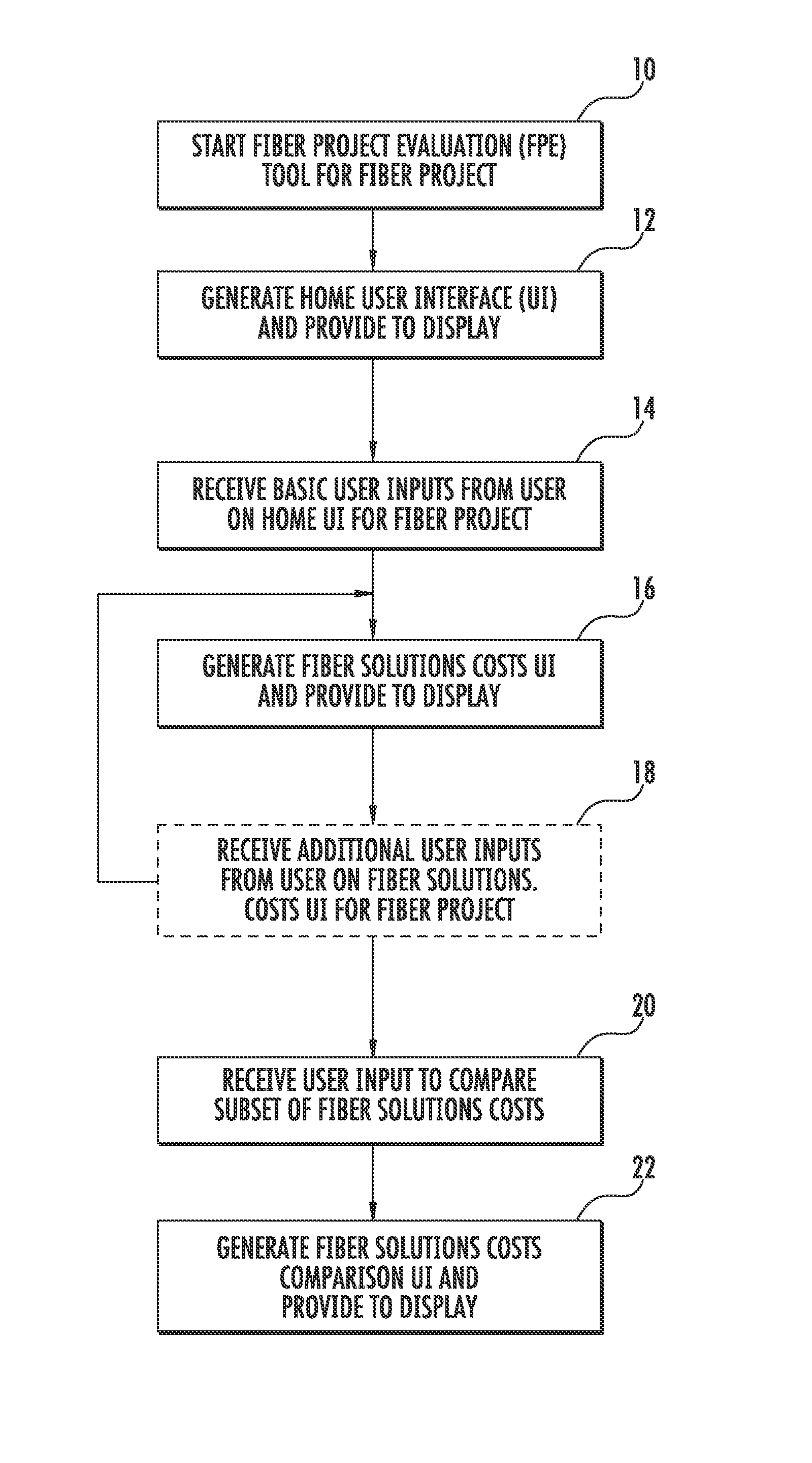
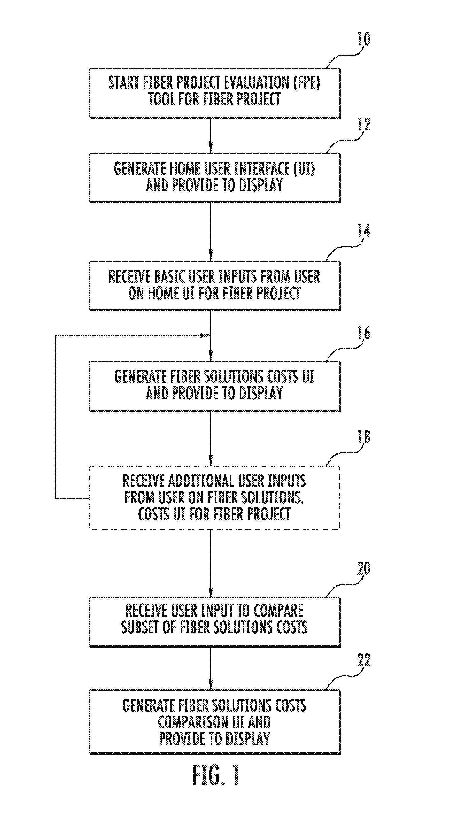
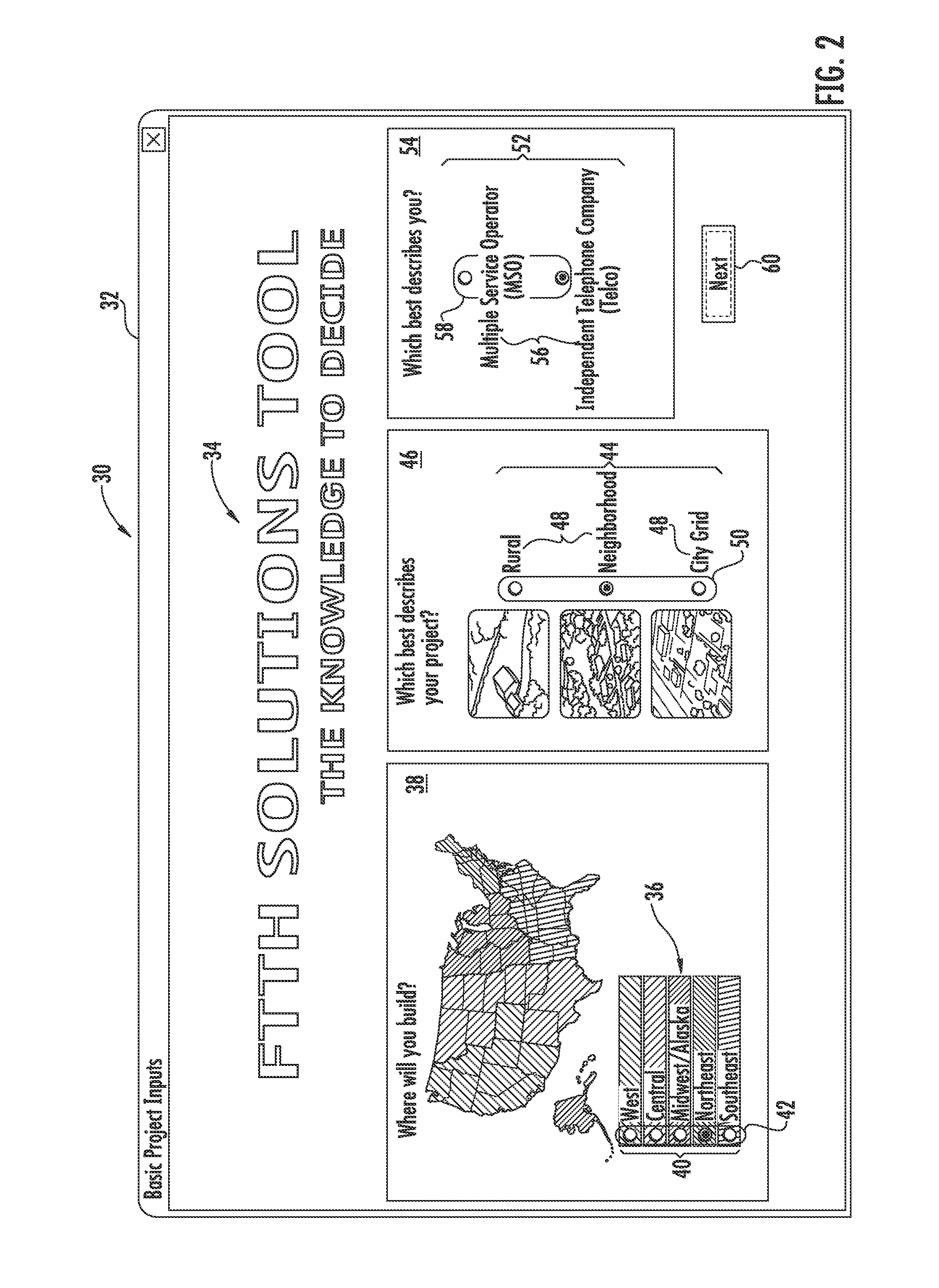
[0006]Embodiments disclosed in the detailed description include fiber project evaluation tools and related methods, graphical user interfaces (GUIs), and computer-readable media to provide and display cost estimates for a plurality of fiber solutions options that can be employed to deploy a fiber optic network for a fiber project. Inputs are provided to allow a user to provide cost-related inputs to customize the cost estimates determined and displayed for the fiber solutions. In this manner, cost estimates can be provided for a variety of fiber solutions at the same time efficiently and visually in a GUI for efficient comparison purposes and to assist in making a choice on a fiber solution for a given fiber project. The cost estimates for the fiber solutions can also be generated and dynamically updated based on providing cost-related inputs to a user that affect the cost estimates for the fiber solutions in an iterative manner. The cost estimates may be useful as preliminary indic...
PUM
 Abstract
Description
Claims
Application Information