Pump drained solar water heating system

Inactive Publication Date: 2012-04-19
GENERAL ELECTRIC CO
View PDF23 Cites 10 Cited by
  • Summary
  • Abstract
  • Description
  • Claims
  • Application Information

AI Technical Summary

Benefits of technology

[0014]Another aspect of the disclosure is that the system pumps the heat transfer fluid to evacuate the plumbing system, and avoids the disadvantages of a pipe installation which relies on gravity to drain the fluid from the collector and piping system.
[0015]Another aspect of the disclosure is that deionized water can be used as the heat tr

Problems solved by technology

Another aspect of the disclosure is that the system automatically removes the heat transfer fluid from the solar collector, upon detection of conditions that could otherwise expose the heat transfer fluid t

Method used


Image

  • Pump drained solar water heating system
  • Pump drained solar water heating system
  • Pump drained solar water heating system

Examples


Embodiment Construction

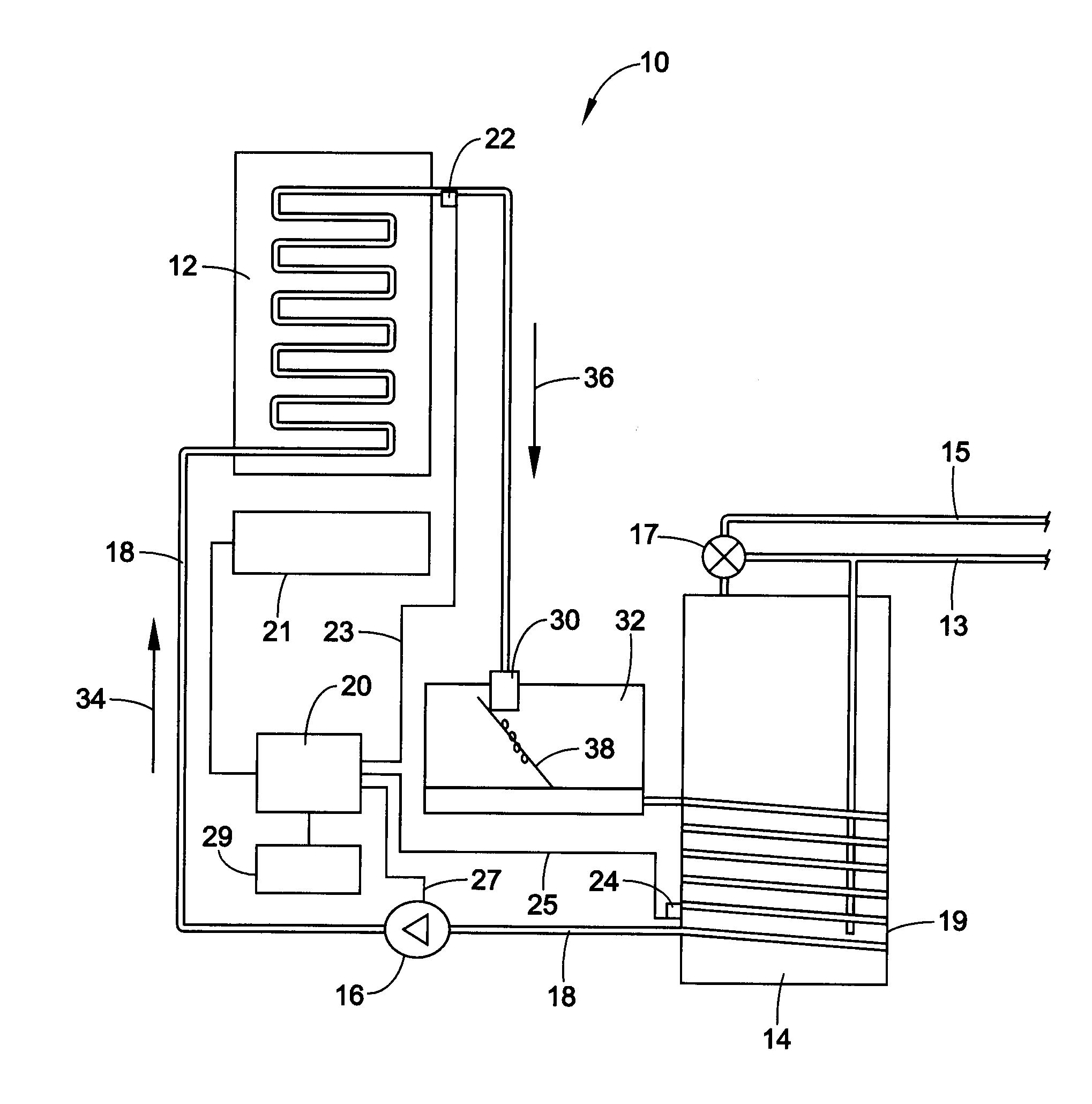
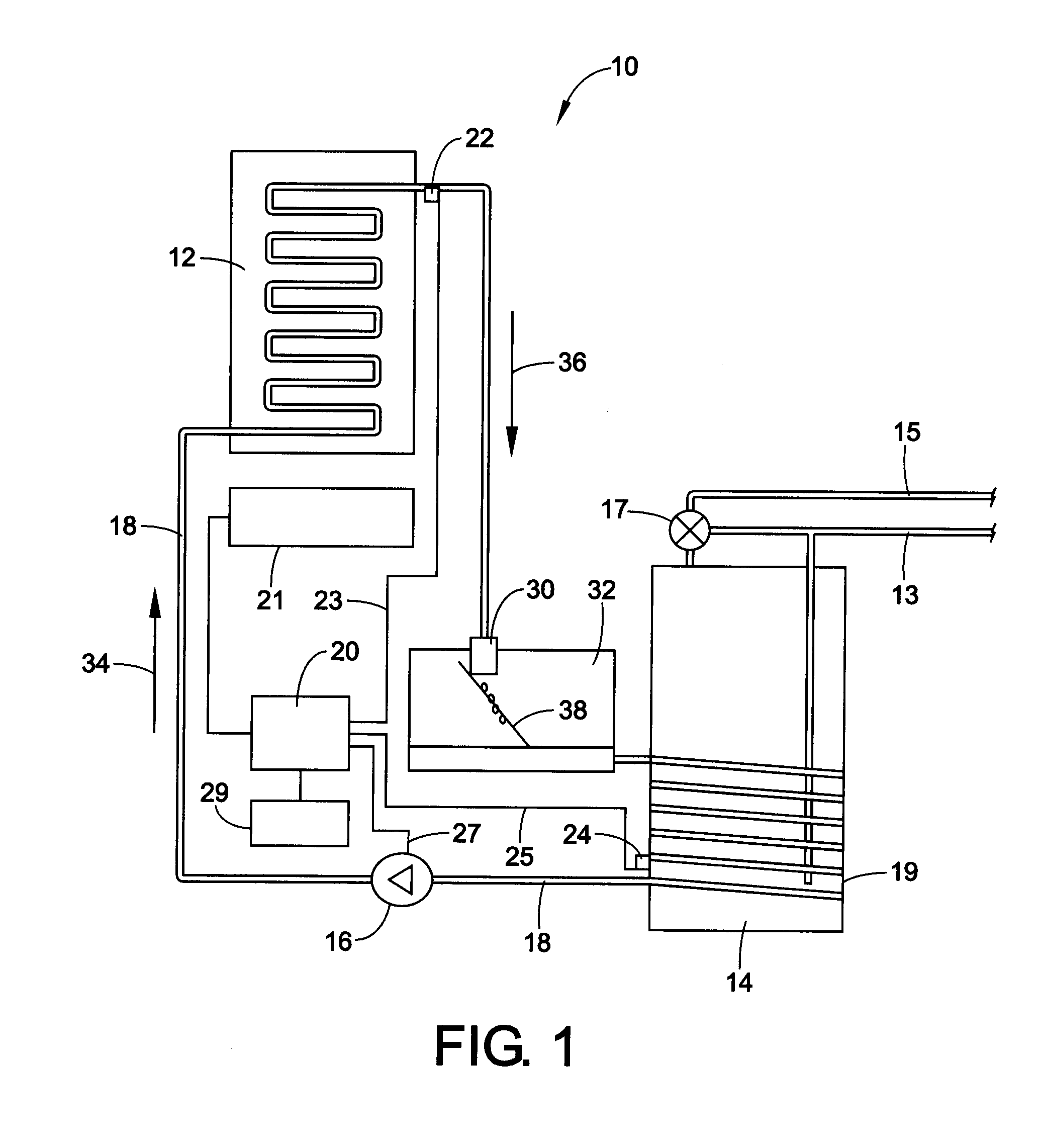
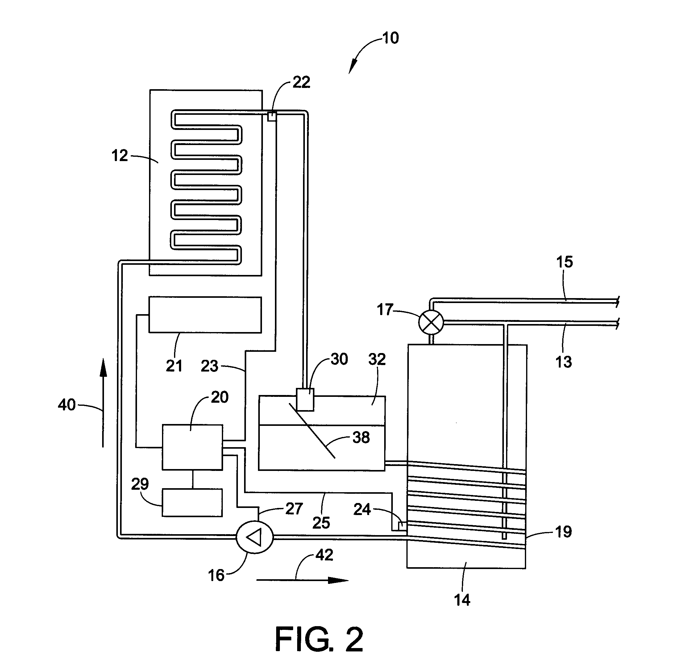
[0025]Referring now to FIG. 1, a solar water heating system 10 in accordance with a preferred embodiment of the present disclosure is shown. The system 10 includes a solar collector 12 which may be of conventional design which collects and provides heat to a heat transfer fluid that then transfers the heat from the collector 12 to water contained in a conventional insulated water heater storage tank 14 having a cold water inlet 13 and a hot water outlet 15. A thermostatic mixing valve 17 is provided at the hot water outlet 15 which mixes cold water from the cold water supply line 13 with the hot water from the hot water outlet line 15 to provide the user with water at the user selected water temperature. Such mixing valves are typically used in solar hot water heating systems because it is desirable to store water in the tank at temperatures which may be higher than that desired for use by the user, for increased energy storage. This is because solar energy is only available periodi...


PUM


Abstract

A pump drained solar water heating system, includes a solar collector; a reversible pump; a reservoir for storing heat transfer fluid; an insulated water storage tank for storing the potable water; piping for fluidically connecting the pump to the solar collector, the heat transfer fluid reservoir; and a heat exchanger; and a controller for operating the pump to transmit fluid in a forward flow or reverse flow direction.

Description

BACKGROUND OF THE DISCLOSURE[0001]Solar water heating systems are made up of components that collect solar energy, transfer the energy to the potable water via a heat exchanger, store the thermal energy, control system operations, deliver hot water where it is needed, and protect the system against freezing. Components can be combined in a variety of ways, but these six basic functions must be met, although some systems are simple enough that passive physics provide the control and motive forces to drive the fluids and heat transfer in the system.[0002]Solar water heating systems can generally be described using the following four terms: direct or indirect and passive or active. Direct systems heat the potable water directly through solar exposure. These systems are typically used in regions with little freeze risk since the potable water is used as the heat transfer fluid and therefore exposed to temperature outside of conditioned space. Indirect systems use a secondary heat transf...

Claims


Application Information

Patent Timeline
IPC IPC(8): F24J2/40F24J2/04
CPCF24D17/0021Y02E10/40F24J2/4634F24S40/60
Inventor ROETKER, JOHN JOSEPH
Owner GENERAL ELECTRIC CO
Why Eureka
Try Eureka