Flexure mount for an optical assembly

a technology of optical assembly and flexure mount, which is applied in the direction of machine supports, instruments, other domestic objects, etc., can solve the problems of large system size, difficult design of systems relying on either solution, and distortion of detected beams

Inactive Publication Date: 2012-04-19
PLX
View PDF0 Cites 10 Cited by
  • Summary
  • Abstract
  • Description
  • Claims
  • Application Information

AI Technical Summary

Benefits of technology

[0015]The assembly alignment system may also be applied to the stiffening member structure with a plurality of alignment pins in the one of either the first stiffening member or second stiffening member, and a plurality of pin receptacles in the other stiffening member. Each alignment pin in registration with one pin hole and one pin receptacle, enabling precision assembly of the stiffening members.

Problems solved by technology

Any deviation from pure translation may cause slight tilting of a plane mirror, leading to distortion in the detected beam.
Systems relying on either such solution are difficult to design, relatively large, expensive and present maintenance issues.
The extremely high machining tolerances required of such an arrangement and related issue of assembling same, result in high costs of both manufacture and maintenance.
In addition, such pure translation flexure mounts are not typically useful for the relatively large displacements necessary for high resolution applications.
The need for greater displacement can be achieved, but primarily through great cost of highly engineered precision instrumentation.
Such forces and resultant distortions introduce inaccuracies into the optical measurements.
A similarly pervasive issue concerns thermal and mechanical forces.

Method used


Image

  • Flexure mount for an optical assembly
  • Flexure mount for an optical assembly
  • Flexure mount for an optical assembly

Examples


Embodiment Construction

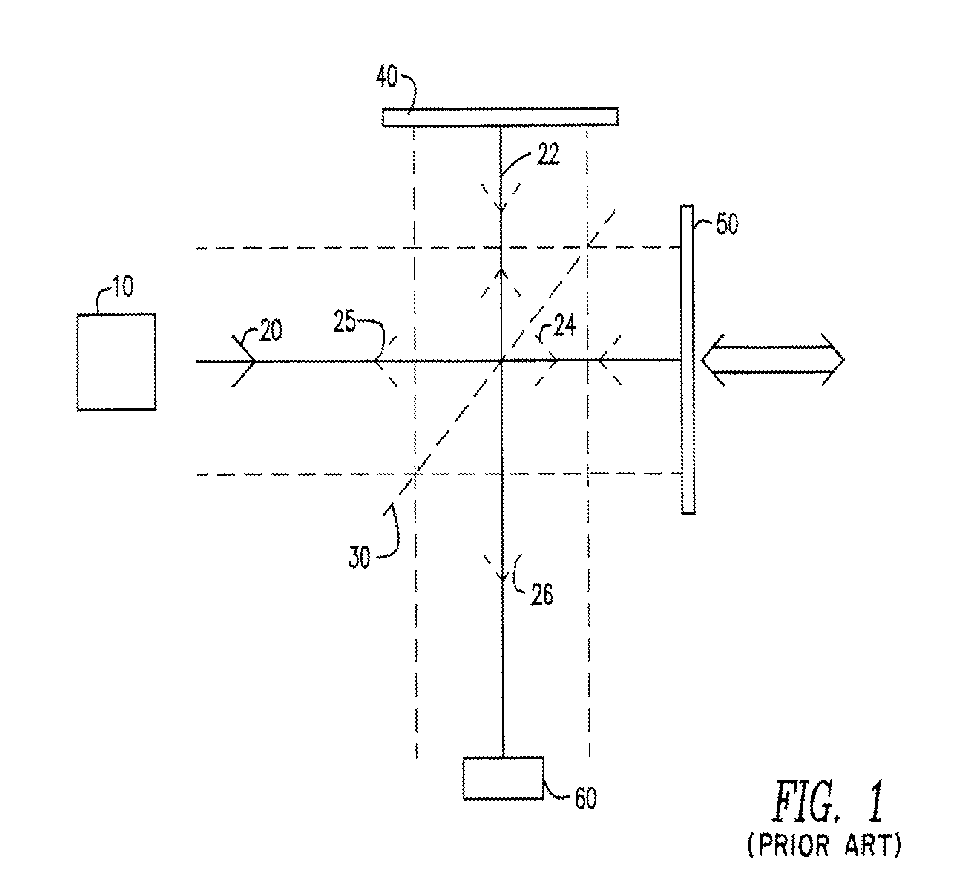
[0034]Referring to FIG. 1, the general principals of a standard Michelson interferometer are shown. The Michelson interferometer has a radiation source 10 which sends a single radiation beam 20 towards beamsplitter 30 which is situated at an angle to two mirrors, a fixed mirror 40 and a movable mirror 50. Radiation beam 20 is partially reflected toward fixed mirror 40 in the form of radiation beam 22, and is partially translated through beamsplitter 30 towards movable mirror 50 as radiation beam 24. Beam 22 is then reflected off of fixed mirror 40, back towards beamsplitter 30, where it is once again partially split, sending some radiation 25 back towards source 10, and some radiation 26 toward detector 60. Similarly, beam 24 reflects off of movable mirror 50 and is reflected back toward beamsplitter 30. Here also, beam 24 is again split, sending some radiation back to source 10 and other radiation 26 toward detector 60.

[0035]Detector 60 measures the interference between the two rad...


PUM


Abstract

A flexure mount for economically producing pure translational motion with no arcuate or error motion in the vertical direction utilizing alignment pins and parts reducing structures including monolithic springs. A low profile embodiment utilizes a compound monolithic spring. The flexure mount may be used to translate a mirror or retroreflector in a purely linear direction of precisely controlled and known distance, useful in myriad interferometer applications including spectroscopy.

Description

CROSS-REFERENCE TO RELATED APPLICATION[0001]This application is a Divisional application of U.S. patent application Ser. No. 12 / 505,279, filed Jul. 17, 2009, which is presently pending and claims priority to, and the benefit of, provisional U.S. application Ser. No. 61 / 081,547, filed on Jul. 17, 2008, the entireties of which applications are incorporated herein by reference in their entireties.FIELD OF THE INVENTION[0002]The present invention is in the field of mechanisms for economically producing pure translational motion with no arcuate or error motion in the vertical direction. Such pure translational motion is critical for precision instrumentation applications. One such application is the movement of optical assemblies such as retroreflectors in interferometer / spectroscopy applications.BACKGROUND OF THE INVENTION[0003]Fourier transform infrared (“FTIR”) spectrometers are well known in the art. Michelson interferometers function by splitting a beam of electromagnetic radiation ...

Claims


Application Information

Patent Timeline
Patent Type & Authority Applications(United States)
IPC IPC(8): G02B7/00
CPCG12B5/00
Inventor JACOBSON, ALEXANDERBLEIER, ZVI
Owner PLX
Why Eureka
Try Eureka