Flexible workpiece assembling method

a flexible workpiece and assembling method technology, applied in the direction of process control, process control, instruments, etc., can solve the problems of inability to accurately perform the difficulty of accurately performing the assembling operation of such a flexible workpiece by using a machine, and the inability to adapt to the needs of the user

Inactive Publication Date: 2009-01-29
FANUC LTD
View PDF3 Cites 48 Cited by
  • Summary
  • Abstract
  • Description
  • Claims
  • Application Information

AI Technical Summary

Benefits of technology

[0019]Thus, as in the sixth aspect, when the flexible workpiece is pushed thereinto, manual operation by an operator can be eliminated, and therefore, the pushing operation of the flexible workpiece can be accomplished by using only the robots. The pushing means may be a dedicated tool that is attached to the hand of the robot, or an end portion of the robot may be used as the pushing means.

Problems solved by technology

Therefore, it is difficult to accurately perform the assembling operation of such a flexible workpiece by using a machine.
Further, even if a specified machine can perform the assembling operation of the flexible workpiece automatically, such machine may be too big and there is also a tendency for the machine to be expensive and may not be versatile.
However, in the case of a flexible workpiece that is relatively small and easy to bend such as, for example, a rubber hose, even if the movement correction amount is determined based on the detection value of the force sensor as disclosed in Japanese Unexamined Patent Publication No. 8-174460, this movement correction amount may not always be accurate.
In such a case, the flexible workpiece may not be able to be accurately assembled onto a nonflexible object and, in addition, the flexible workpiece may be broken or torn when it is transferred.
Therefore, when the flexible workpiece is relatively small and easy to bend, more delicate control is required.

Method used


Image

  • Flexible workpiece assembling method
  • Flexible workpiece assembling method
  • Flexible workpiece assembling method

Examples


Embodiment Construction

[0027]Hereinafter, the embodiments of the present invention will be described in detail with reference to the accompanying drawings. Throughout the drawings like elements are designated by like reference numerals. For ease of understanding, the scale of these drawings has been changed appropriately.

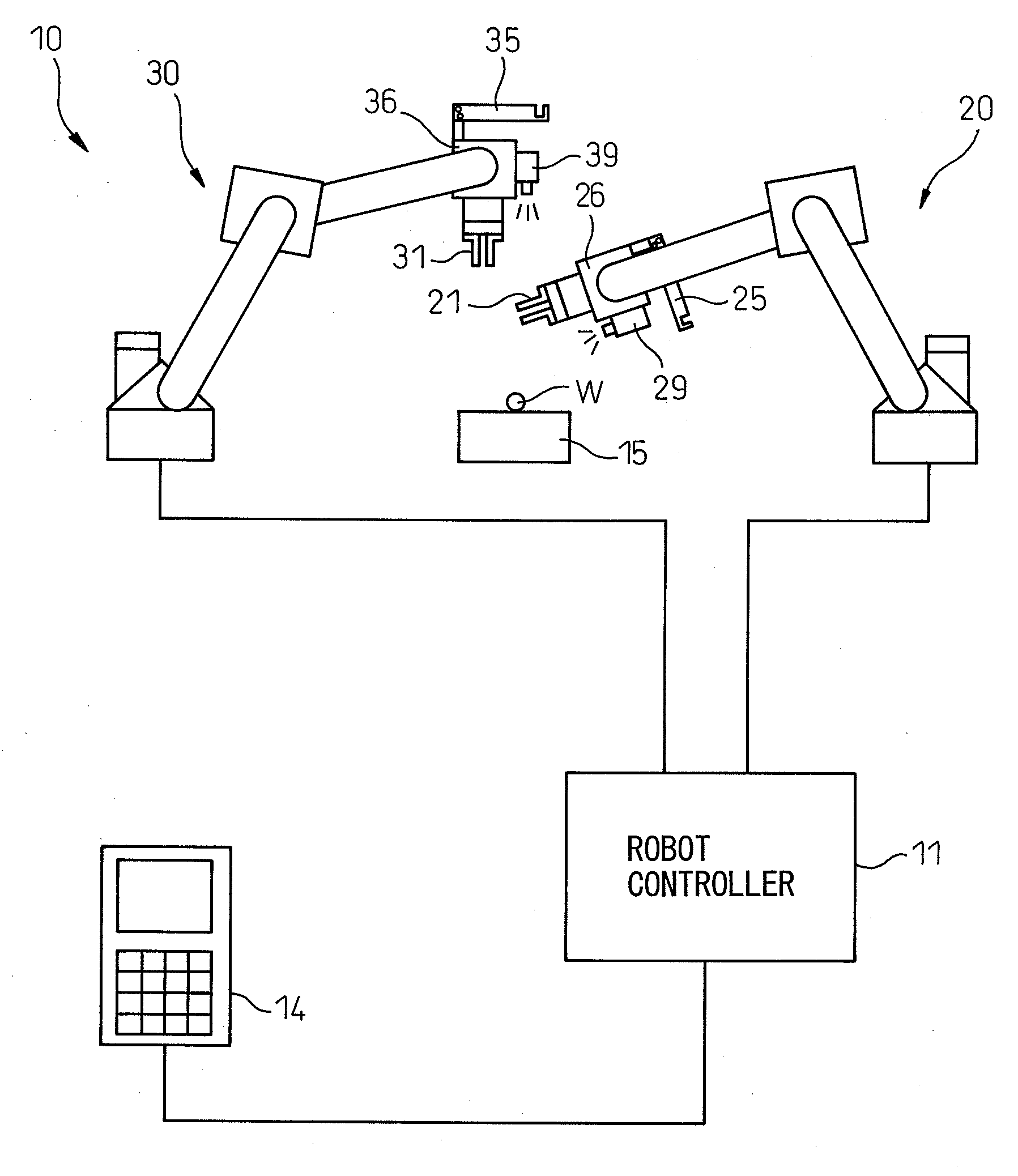
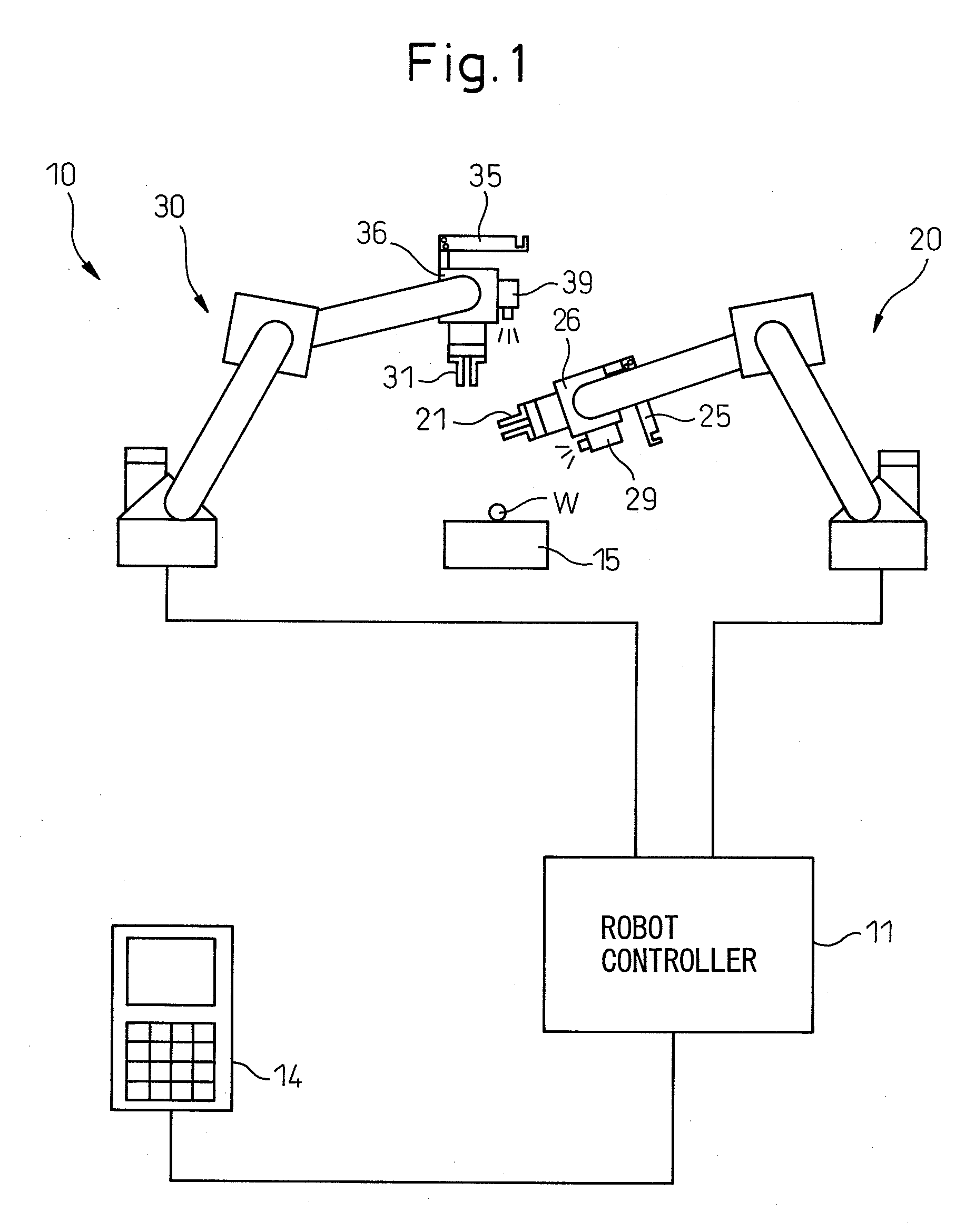
[0028]FIG. 1 is a conceptual diagram of a robot program adjustment device according to the present invention. As shown in FIG. 1, a robot system 10 includes: a first handling robot 20 (hereinafter referred to as a first robot 20) comprising a hand 21; and a second handling robot 30 (hereinafter referred to as a second robot 30) comprising a hand 31. In FIG. 1, the first robot 20 and the second robot 30 are six-degree-of-freedom articulated robot arms.

[0029]As shown in the figure, the first robot 20 and the second robot 30 comprise visual detection means or cameras 29 and 39, respectively, which are connected to a robot controller 11 described below. Further, a unit 36 comprising the hand ...


PUM

PropertyMeasurementUnit
flexibleaaaaaaaaaa

Abstract

A flexible workpiece assembling method for assembling a flexible workpiece (W) with an object by using a first robot comprising a first hand and a second robot comprising a second hand includes the steps of: gripping a first portion of the flexible workpiece by the first hand and gripping a second portion of the flexible workpiece different from the first portion by the second hand; moving the flexible workpiece to the object through a cooperating operation of the first and second robots; deforming the flexible workpiece into a shape corresponding to the nonflexible object by the first and second robots; and assembling the flexible workpiece onto the nonflexible object by the first and second robots. As a result, the flexible workpiece can be accurately assembled onto the nonflexible object without breaking or tearing. The first and second robots may comprise a pushing means for pushing the flexible workpiece into the object.

Description

BACKGROUND OF THE INVENTION[0001]1. Field of the Invention[0002]The present invention relates to a flexible workpiece assembling method for assembling a flexible workpiece onto a nonflexible object by using two robots equipped with hands.[0003]2. Description of the Related Art[0004]Generally, an assembling operation of a flexible workpiece such as a resin molded article and the like is performed assuming that the flexible workpiece is deformed and assembled on a nonflexible object. Therefore, it is difficult to accurately perform the assembling operation of such a flexible workpiece by using a machine. Further, even if a specified machine can perform the assembling operation of the flexible workpiece automatically, such machine may be too big and there is also a tendency for the machine to be expensive and may not be versatile. As a result, the assembling operation of the flexible workpiece is typically performed by a manual operation.[0005]Japanese Unexamined Patent Publication No....

Claims


Application Information

Patent Timeline
Patent Type & Authority Applications(United States)
IPC IPC(8): B23P11/00
CPCB25J9/1682B25J9/1687G05B2219/39109G05B2219/39123Y10T29/49829G05B2219/40052G05B2219/40307G05B2219/45064G05B2219/39469
Inventor HARIKI, KAZUOODA, MASARUKAJIO, SHIGENORINIHEI, RYO
Owner FANUC LTD
Why Eureka
Try Eureka