Position compensating differential locking mechanism

a locking mechanism and differential technology, applied in mechanical devices, transportation and packaging, gearing, etc., can solve the problems of only being able to engage the locking mechanism, vehicle can become immobilized, and differential will reduce the torque supplied to the other wheel

Inactive Publication Date: 2004-12-28
SCHAFER DRIVELINE LLC
View PDF9 Cites 12 Cited by
  • Summary
  • Abstract
  • Description
  • Claims
  • Application Information

AI Technical Summary

Benefits of technology

A differential in accordance with the present invention has one or more advantages as compared to the prior art. First, the differential can operate freely during vehicle travel regardless of the level of engagement between the opposed clutch members. Second, the inventive differential may eliminate the need for manual operation of the differential locking mechanism. Third, the locking mechanism of the inventive differential is compact thereby conserving vehicle space.

Problems solved by technology

However, when one of the wheels loses traction with the ground, due to, for example, wet or icy surfaces, the differential will reduce the amount of torque supplied to the other wheel.
Consequently, the vehicle can become immobilized.
First, the locking mechanism can only be engaged while the vehicle is at rest.
Second, the manual engagement of the locking mechanism requires a physical effort on the part of the operator.
Third, the locking mechanism requires a relatively large amount of space to link the lever and the cable system.
Third, the locking mechanism of the inventive differential is compact thereby conserving vehicle space.

Method used


Image

  • Position compensating differential locking mechanism
  • Position compensating differential locking mechanism
  • Position compensating differential locking mechanism

Examples


Embodiment Construction

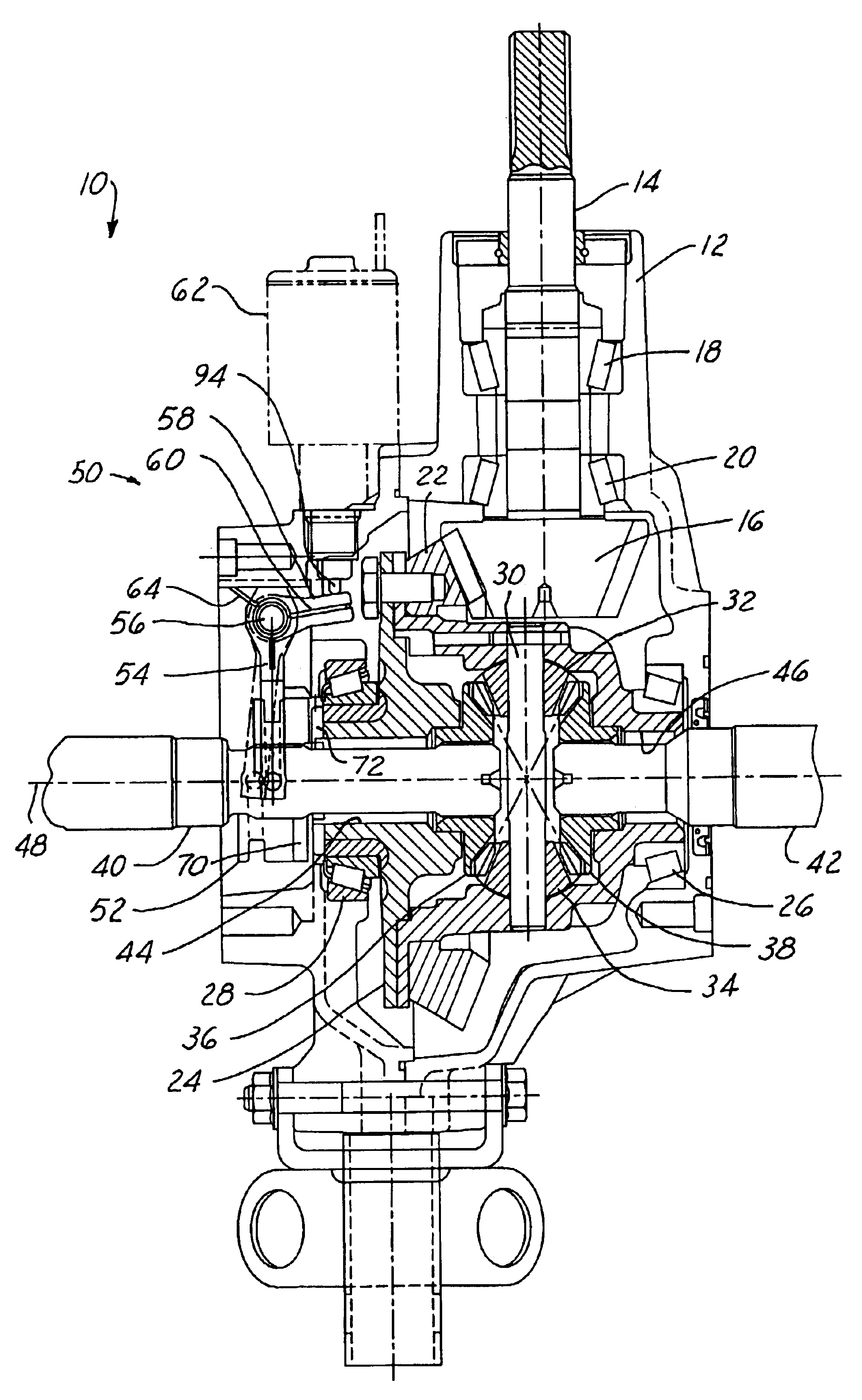
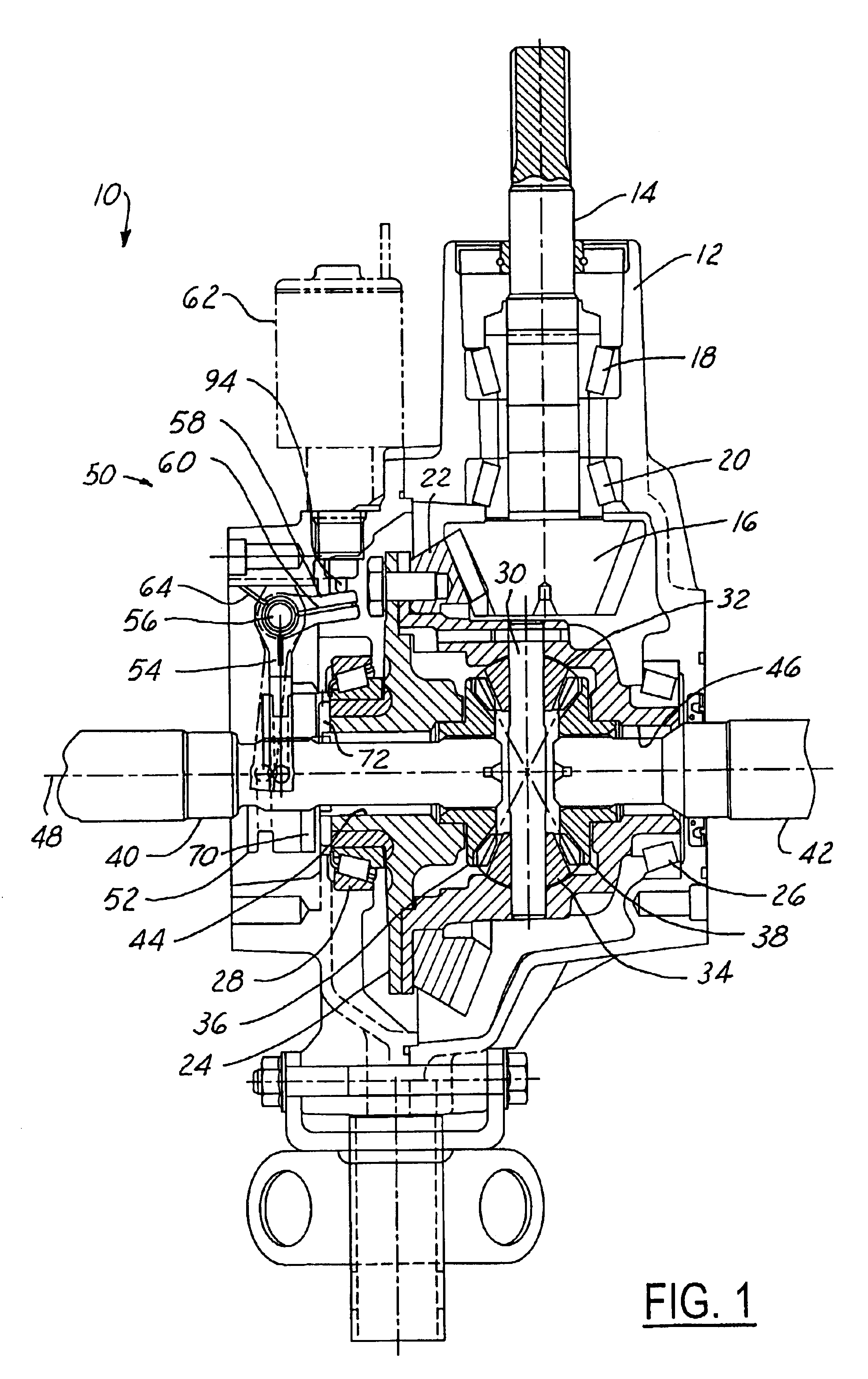
Referring now to the drawings wherein like reference numerals are used to identify identical components in the various views, FIG. 1 illustrates a cross-sectional view of a differential 10 in accordance with one embodiment of the present invention. Differential 10 is provided to enable two wheels (not shown) in a vehicle that are disposed about a common rotational axis to rotate at different speeds. Differential 10 may include several conventional components known to those of skill in the art. In particular, differential 10 may include a housing 12 composed of multiple members and a pinion shaft 14 that extends through an opening in housing 12 and supports a pinion gear 16. The pinion shaft 14 may be supported for rotation within housing 12 by bearings 18, 20 and may be driven by a power input shaft (not shown). Differential 10 may further include a ring gear 22 coupled to or integral with a differential case 24 and driven by pinion gear 16. Case 24 is supported within housing 12 by...


PUM


Abstract

A differential with an improved locking mechanism is provided. The differential includes first and second clutch members in the form of a differential case having a first set of teeth and a an axle shaft mounted clutch collar having a second set of teeth. A yoke urges the clutch into an out of engagement and is supported on a pivot shaft. The yoke is selectively urged in one direction by an actuator acting on a lever on the pivot shaft. The lever is coupled to the yoke by a spring. The yoke is urged in an opposite direction by one or more return springs mounted on the same pivot shaft. The compact nature of the locking mechanism and the balance of forces provided by the springs and actuator provide an inexpensive and reliable locking mechanism.

Description

1. Field of the InventionThe present invention relates to a differential, and more particularly, to a position compensating differential locking mechanism.2. Discussion of Related ArtDifferential gear mechanisms, simply referred to as differentials, are well known devices frequently used in the drive trains of most vehicles. The differential is usually connected between an input driving shaft {typically a drive shaft from the vehicle engine} and a pair of output driven shafts (typically a pair of axle shafts connected to the vehicle wheels). The differential distributes torque from the input shaft equally to the two output shafts, while permitting such output shafts to rotate at different speeds under certain conditions. As a result, torque is supplied to both wheels of the vehicle as it negotiates a turn, while permitting the outside wheel to turn faster than the inside wheel.In a conventional open differential, the movements of the various internal components of the differential a...

Claims


Application Information

Patent Timeline
Patent Type & Authority Patents(United States)
IPC IPC(8): F16H48/00F16H48/30F16H48/24F16H48/08B60K23/04F16H48/20F16H48/34F16H48/42
CPCF16H48/08F16H48/24F16H48/30F16H48/34F16H2048/423F16H2048/204F16H2048/346
Inventor BUSCH, CHARLES R.REASER, HOWARD
Owner SCHAFER DRIVELINE LLC
Why Eureka
Try Eureka