Marine vessel propulsion apparatus

a propulsion apparatus and marine technology, applied in marine propulsion, outboard propulsion units, vessel construction, etc., can solve the problems of less smooth steering, increased posture holding force of outboard motors, and less than optimal response of outboard motors, so as to reduce the transmission of vibration of outboard motors to the hull, the degree of freedom of design of the first mount and the second mount can be further increased, and the effect of reducing the transmission of vibration of outboard motors

Active Publication Date: 2012-04-19
YAMAHA MOTOR CO LTD
View PDF5 Cites 6 Cited by
  • Summary
  • Abstract
  • Description
  • Claims
  • Application Information

AI Technical Summary

Benefits of technology

[0007]In detail, as described above, vibration of the outboard motor is attenuated by the upper mounts and the lower mounts. For example, by making the upper mounts and the lower mounts soft, the vibration transmissibility can be reduced and transmission of vibration of the outboard motor to the hull can be further minimized. However, if the upper mounts and the lower mounts are soft, the force to hold the outboard motor on the hull (posture holding force of the outboard motor) is reduced. If the posture holding force of the outboard motor is weak, the outboard motor easily wobbles, so that the steering is less smooth. Specifically, when changing the direction of the outboard motor by turning the rudder arranged to steer the marine vessel, the response of the outboard motor can be less than optimal. On the other hand, if the upper mounts and the lower mounts are made hard, the posture holding force of the outboard motor increases, however, the vibration transmissibility increases.
[0012]In detail, vibration of the outboard motor is blocked by the first mount and the second mount that have elasticity. The propulsive force generated by the outboard motor is transmitted to the first joint portion and the second joint portion from the outboard motor via upper mounts and lower mounts. Further, the propulsive force generated by the outboard motor is transmitted from the outboard motor to the support portion. Thus, the propulsive force is transmitted from the outboard motor to the hull not only via the first mount and the second mount but also via the support portion. In other words, the outboard motor is supported by the first joint portion, the second joint portion, and the support portion, and by providing the support portion, the points of support for the outboard motor are increased.
[0013]To transmit a high load only by the first mount and the second mount when the space in which the first mount and the second mount are disposed is narrow, mounts with high elastic coefficients must be used as the first mount and the second mount. However, if the elastic coefficients of the first mount and the second mount are high, vibration of the outboard motor is easily transmitted to the hull. On the other hand, by increasing the points of support for the outboard motor by providing the support portion, the load to be applied to the first mount and the second mount can be reduced. Specifically, displacements of the first mount and the second mount can be minimized. Therefore, as long as determinate displacements are allowed, the elastic coefficients of the first mount and the second mount can be reduced. Accordingly, transmission of vibration of the outboard motor to the hull can be minimized. Further, the support portion is provided, so that even if the elastic coefficients of the first mount and the second mount are reduced, a load with the same magnitude as in the case where the support portion is not provided can be transmitted from the outboard motor to the hull. Further, by providing the support portion, the points of support for the outboard motor are increased, so that the posture holding force of the outboard motor can be increased.
[0017]The support portion may include a lateral support portion arranged to support the outboard motor at a position separate from the first mount and the second mount in the right-left direction. In this case, the first joint portion, the second joint portion, and the support portion can support the outboard motor at a plurality of points separate from each other in the right-left direction. Accordingly, the outboard motor can be stabilized.
[0018]The marine vessel propulsion apparatus may further include a third mount having elasticity, and the support portion may support the outboard motor via the third mount. In this case, the outboard motor is supported by the first mount, the second mount, and the third mount. Vibration of the outboard motor is blocked by the third mount in addition to the first mount and the second mount. Further, the propulsive force generated by the outboard motor is transmitted by the third mount in addition to the first mount and the second mount. Therefore, the degree of freedom of the design of the first mount and the second mount can be further increased. Accordingly, transmission of vibration of the outboard motor to the hull can be minimized, and the posture holding force of the outboard motor can be increased.

Problems solved by technology

If the posture holding force of the outboard motor is weak, the outboard motor easily wobbles, so that the steering is less smooth.
Specifically, when changing the direction of the outboard motor by turning the rudder arranged to steer the marine vessel, the response of the outboard motor can be less than optimal.
On the other hand, if the upper mounts and the lower mounts are made hard, the posture holding force of the outboard motor increases, however, the vibration transmissibility increases.
Thus, reduction in vibration transmissibility and an increase in posture holding force of the outboard motor counter each other, so that it is difficult to reduce the vibration transmissibility and increase the posture holding force of the outboard motor provided by the upper mounts and the lower mounts.
Further, the upper mounts and the lower mounts are disposed inside the outboard motor, so that the numbers and sizes of the upper mounts and the lower mounts are limited.
Therefore, ranges of settable elastic coefficients and contraction amounts, etc., are limited, so that the degree of freedom of the design is small.
Therefore, it is more difficult to realize both of a reduction in vibration transmissibility and an increase in posture holding force of the outboard motor.

Method used


Image

  • Marine vessel propulsion apparatus
  • Marine vessel propulsion apparatus
  • Marine vessel propulsion apparatus

Examples


first preferred embodiment

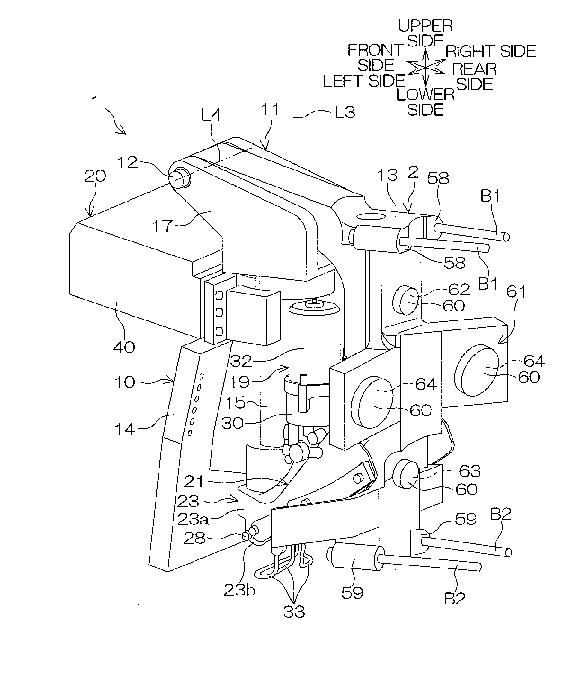
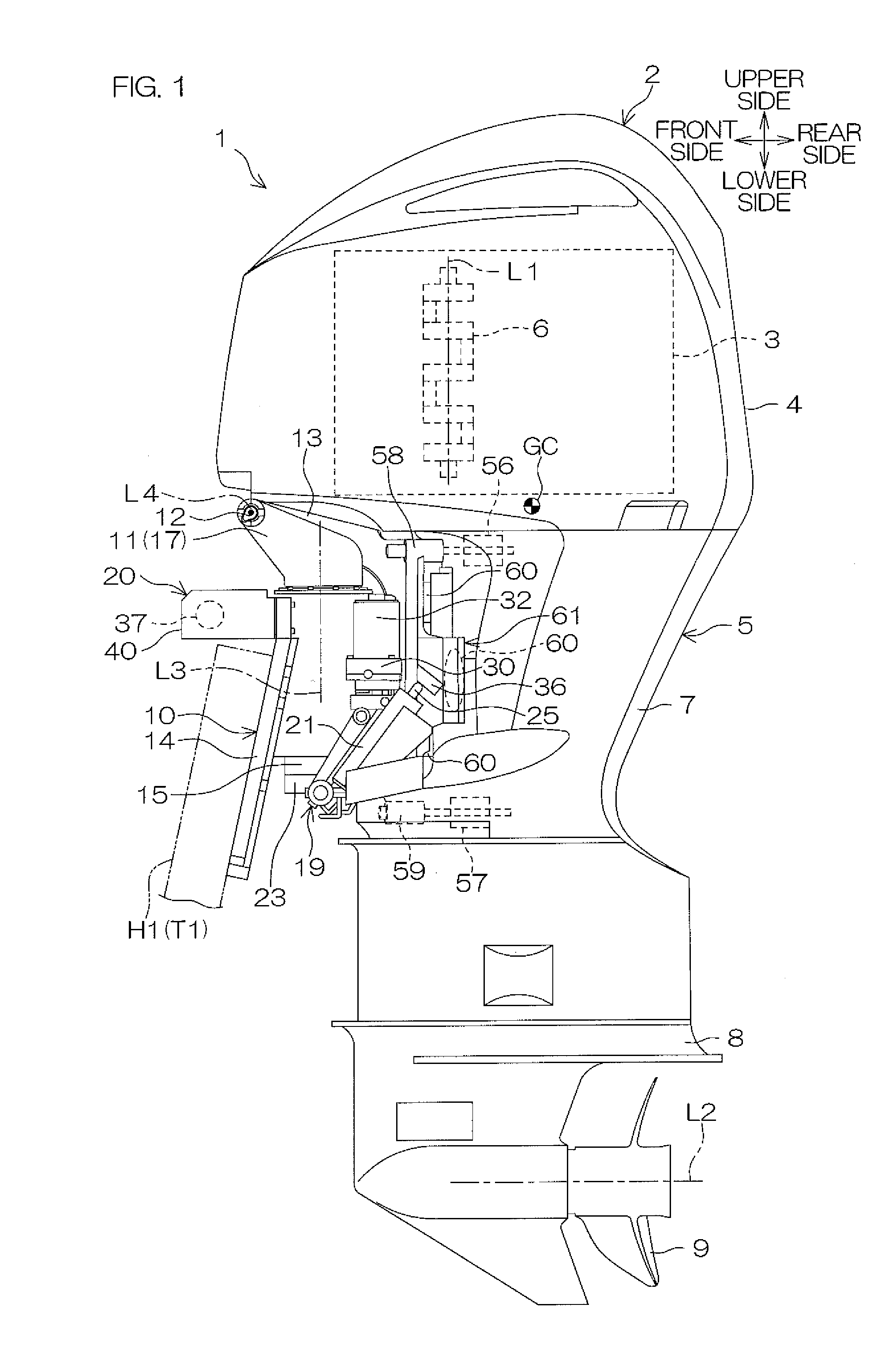
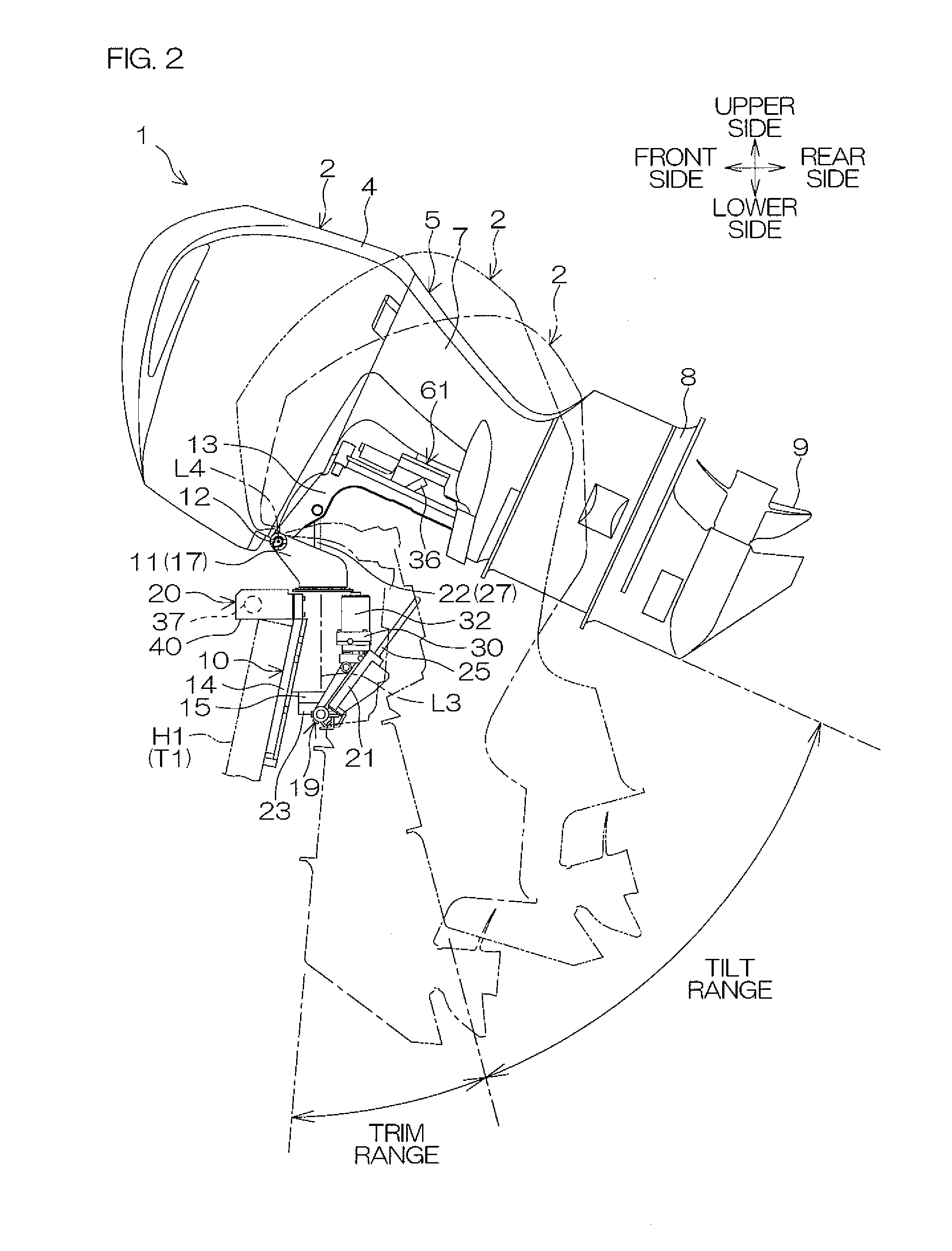
[0056]FIG. 1 and FIG. 2 are side views of a first marine vessel propulsion apparatus 1 according to a first preferred embodiment of the present invention. FIG. 3 is a plan view of the first marine vessel propulsion apparatus 1 according to the first preferred embodiment of the present invention. FIG. 4A is a perspective view of a portion of the first marine vessel propulsion apparatus 1 according to the first preferred embodiment of the present invention. FIG. 4B is an exploded perspective view of a portion of the first marine vessel propulsion apparatus 1 according to the first preferred embodiment of the present invention. FIG. 4C is an exploded view of a portion of the first marine vessel propulsion apparatus 1 according to the first preferred embodiment of the present invention. “GC” in FIG. 1 indicates the gravity center of the outboard motor 2.

[0057]The first marine vessel propulsion apparatus 1 includes an outboard motor 2. The outboard motor 2 is attached to a transom T1 pro...

second preferred embodiment

[0100]FIG. 17 is an enlarged partial sectional view of a portion of a first marine vessel propulsion apparatus 201 according to a second preferred embodiment of the present invention. FIG. 18 is a back view of a tilt bracket 213 and an arrangement relating thereto according to the second preferred embodiment of the present invention. FIG. 19 is a schematic plan view for describing a supported state of an outboard motor 2 according to the second preferred embodiment of the present invention. In FIG. 17 to FIG. 19, constitutional portions equivalent to the portions shown in FIG. 1 to FIG. 16 described above are provided with the same reference numerals as in FIG. 1, etc., and descriptions thereof will be omitted.

[0101]A main difference between the second preferred embodiment and the first preferred embodiment described above is that the first marine vessel propulsion apparatus 201 includes a tilt bracket 213 instead of the tilt bracket 13 according to the first preferred embodiment. A...

third preferred embodiment

[0107]FIG. 20 is a side view of a second marine vessel propulsion apparatus 301 according to a third preferred embodiment of the present invention. FIG. 21A is a perspective view of a portion of the second marine vessel propulsion apparatus 301 according to the third preferred embodiment of the present invention. FIG. 21B is an exploded perspective view of a portion of the second marine vessel propulsion apparatus 301 according to the third preferred embodiment of the present invention. FIG. 21C is an exploded view of a portion of the second marine vessel propulsion apparatus 301 according to the third preferred embodiment of the present invention. FIG. 22 is a partial side view of a portion of the second marine vessel propulsion apparatus 301 according to the third preferred embodiment of the present invention.

[0108]The second marine vessel propulsion apparatus 301 includes the outboard motor 2, the transom bracket 10, a steering shaft 311, the tilt shaft 12, and the tilt bracket 1...


PUM


Abstract

A marine vessel propulsion apparatus includes an outboard motor, a transom bracket, a steering shaft, a first mount, a second mount, a tilt bracket, a tilt mechanism, and a steering mechanism. The tilt bracket is attached to a transom via the transom bracket and the steering shaft. The outboard motor is joined to the tilt bracket. The tilt bracket includes a first joint portion joined to the outboard motor via a first mount, a second joint portion joined to the outboard motor via a second mount, and a support portion arranged to support the outboard motor at a height different from heights of the first mount and the second mount.

Description

BACKGROUND OF THE INVENTION[0001]1. Field of the Invention[0002]The present invention relates to a marine vessel propulsion apparatus.[0003]2. Description of Related Art[0004]A conventional marine vessel propulsion apparatus is described in, for example, U.S. Pat. No. 7,244,152. This marine vessel propulsion apparatus includes a transom mount structure, an intermediate member, an outboard motor, upper mounts, and lower mounts.[0005]The transom mount structure is attached to the transom of a hull. The intermediate member is attached to the transom via the transom mount structure. The intermediate member is attached to the outboard motor via the upper mounts and the lower mounts. The upper mounts and the lower mounts have elasticity. The upper mounts and the lower mounts are housed inside the outboard motor. The propulsive force generated by the outboard motor is transmitted to the intermediate member via the upper mounts and the lower mounts. Vibration of the outboard motor is attenu...

Claims


Application Information

Patent Timeline
Patent Type & Authority Applications(United States)
IPC IPC(8): B63H20/10B63H20/12
CPCB63H20/12B63H20/10
Inventor TAKASE, HIROAKI
Owner YAMAHA MOTOR CO LTD
Why Eureka
Try Eureka