

Sonotrode and anvil energy director grids for narrow/complex ultrasonic welds of improved durability
- Summary
- Abstract
- Description
- Claims
- Application Information
AI Technical Summary
Benefits of technology
Problems solved by technology
Method used
Image

Examples
first embodiment
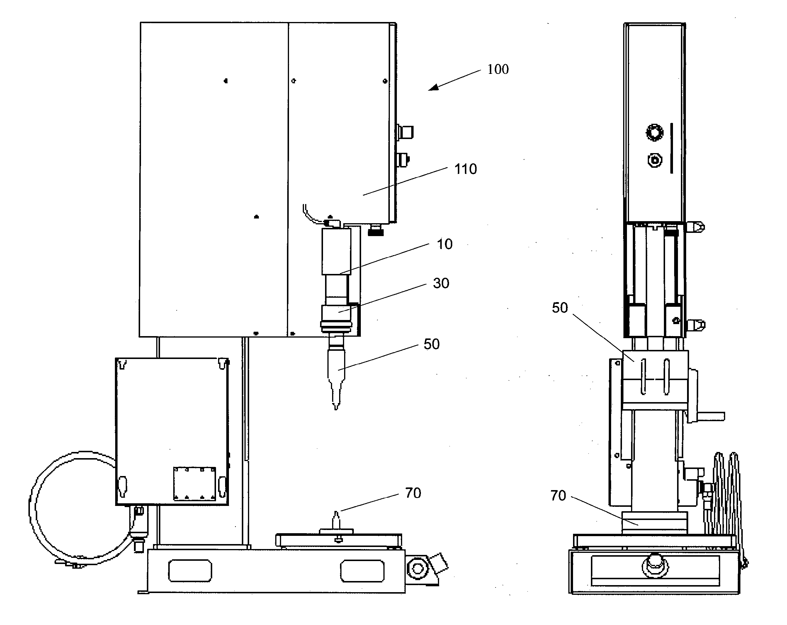
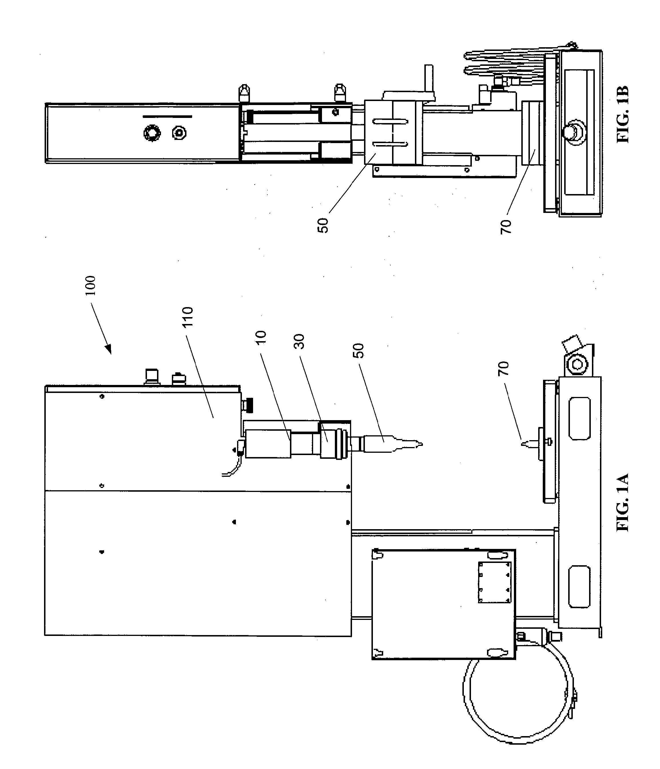
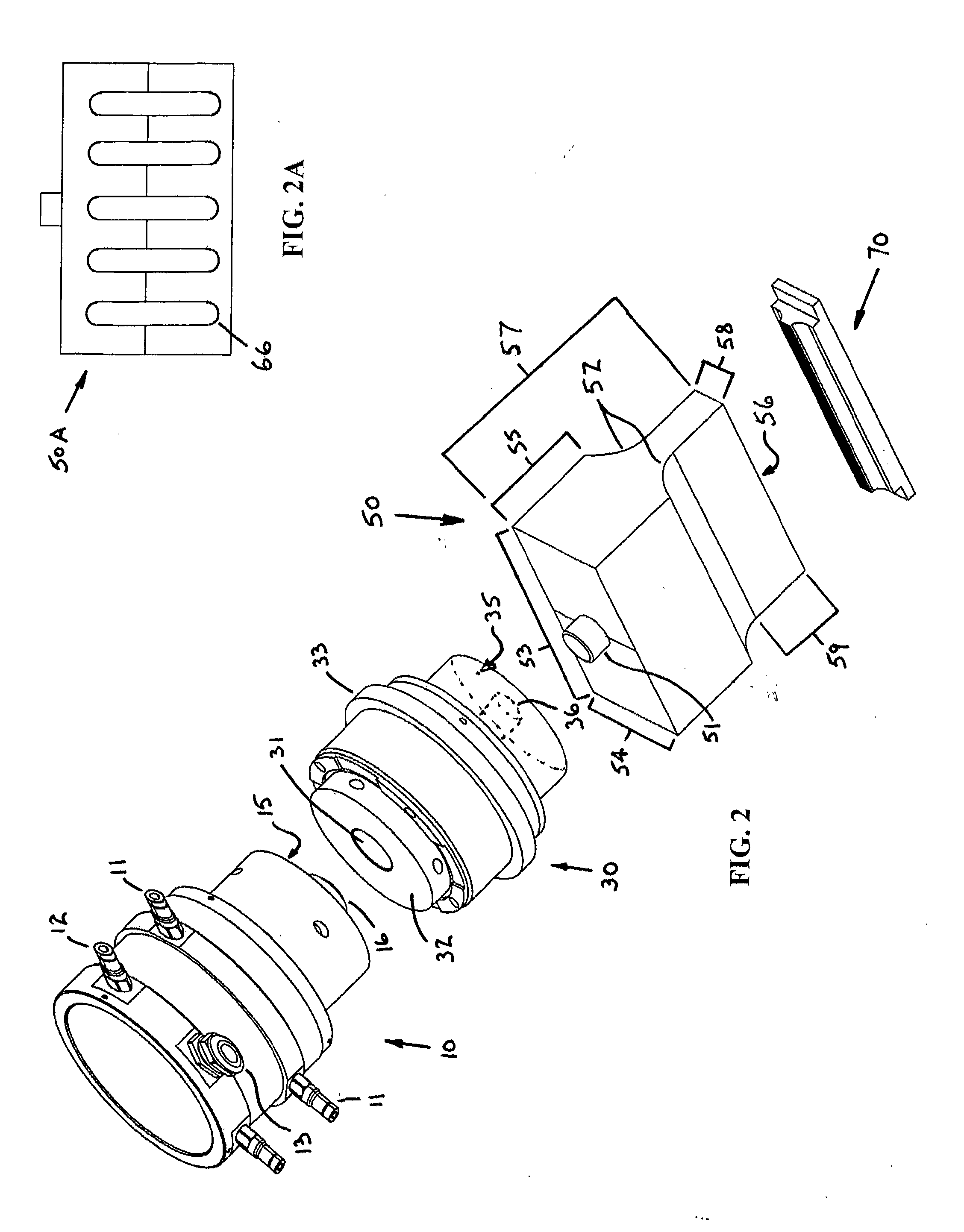
[0058]FIG. 2 shows the present invention, where the stack includes a converter 10, a booster 30, a sonotrode 50, and an anvil 70 that may be used to weld straight patterns. The converter 10 may be comprised of electrical connectors 11, 12, and 13. The converter 10 may also comprise a flat surface 15 from which protrudes a cylindrical connection means 16 that may be received in a corresponding cylindrical opening 31 in flat surface 32 of booster 30, for attachment of the converter to the booster. The booster 30 may have a flange 33 for use in securing the booster to a press. The booster may have a second flat surface 35 with a cylindrical opening 36 therein, to receive a corresponding cylindrical protrusion 51 of the horn 50. Alternatively, the booster may have a cylindrical protrusion that is received by a cylindrical recess 51A, as seen for the alternative sonotrode 50A of FIG. 10A. The cylindrical protrusion 51 of the horn 50 may protrude from a rectangular block, having a length ...
second embodiment
[0066]In welding according to the present invention, which is advantageous for thinner work pieces, dramatically improved weld durability is achieved by utilizing alignment between the energy director grids whereby the side surfaces of the sonotrode plateaus interlock with the side surfaces of the anvil plateaus (FIG. 11D) in a repeating 3-dimensional pattern, which may include minor elastic deformation of the work pieces. When the work pieces are inserted between the sonotrode and anvil (FIG. 11C), a three-dimensional weld results. The three-dimensional weld exhibits significantly improved durability over that of conventional ultrasonic welds. Depending on the length of the plateau surface utilized on both the anvil and sonotrode, the surface area of contact may be greater or less than the surface area of contact for flat engagement surfaces of the prior art welding machines. Even where the surface area of contact is somewhat less than that of the prior art flat engagement surfaces...
PUM
| Property | Measurement | Unit |
|---|---|---|
| Angle | aaaaa | aaaaa |
| Angle | aaaaa | aaaaa |
| Area | aaaaa | aaaaa |
Abstract
Description
Claims
Application Information