Sublimation systems and associated methods

a technology of sublimation and sublimation, applied in the field of systems for vaporization and sublimation and methods, can solve the problems of carbon dioxide removal, natural gas liquefaction process, carbon dioxide removal,

Active Publication Date: 2012-05-03
THE UNITED STATES AS REPRESENTED BY THE DEPARTMENT OF ENERGY
View PDF5 Cites 11 Cited by
  • Summary
  • Abstract
  • Description
  • Claims
  • Application Information

AI Technical Summary

Problems solved by technology

Carbon dioxide can cause problems in the process of natural gas liquefaction, as carbon dioxide has a freezing temperature that is higher than the liquefaction temperature of methane.
This problem makes it necessary to remove the carbon dioxide from the natural gas prior to the liquefaction process in traditional plants.
The filtration equipment to separate the carbon dioxide from the natural gas prior to the liquefaction process may be large, may require significant amounts of energy to operate, and may be very expensive.
However, the interaction between the solid carbon dioxide and liquid natural gas produces conditions that are very difficult to address with standard heat exchangers.
In addition to collecting in undesirable locations, the carbon dioxide has a tendency to clump together making it even more difficult to flush through the system.
At a temperature when the moving, vaporized natural gas is the only way to transport the solid carbon dioxide crystals, the crystals may begin to clump together due to the tumbling interaction with each other, leading to the aforementioned plugging.
If melting occurs, the surfaces of the crystals becomes sticky causing the crystals to have a tendency to stick to the walls of the heat exchanger, reducing the effectiveness of the heat exchanger and creating localized fouling.
The localized fouling areas may cause the heat exchanger to become occluded and eventually plug if fluid velocities cannot dislodge the fouling.

Method used


Image

  • Sublimation systems and associated methods
  • Sublimation systems and associated methods
  • Sublimation systems and associated methods

Examples


Embodiment Construction

[0016]Some of the illustrations presented herein are not meant to be actual views of any particular material, device, or system, but are merely idealized representations which are employed to describe the present invention. Additionally, elements common between figures may retain the same numerical designation.

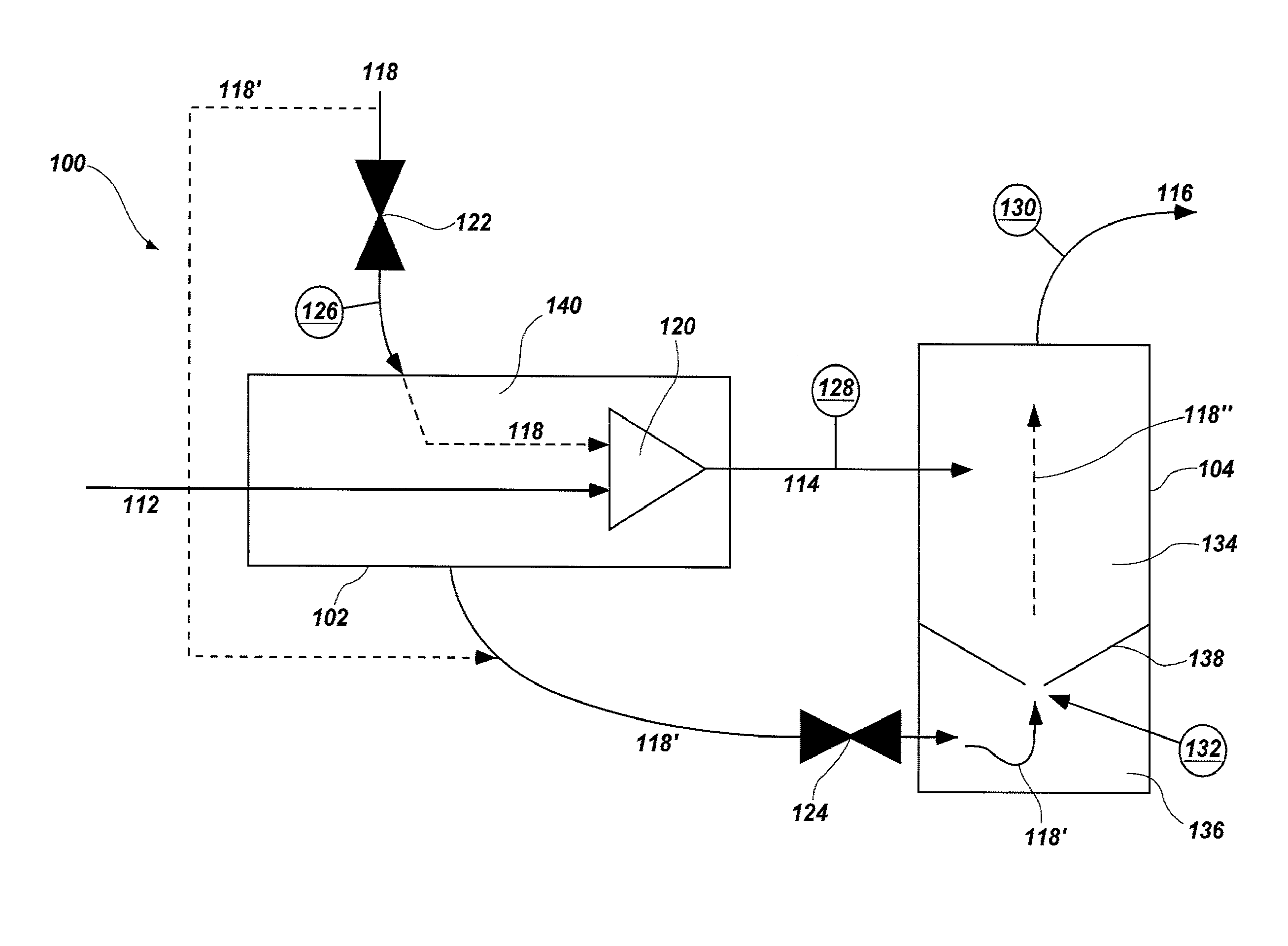
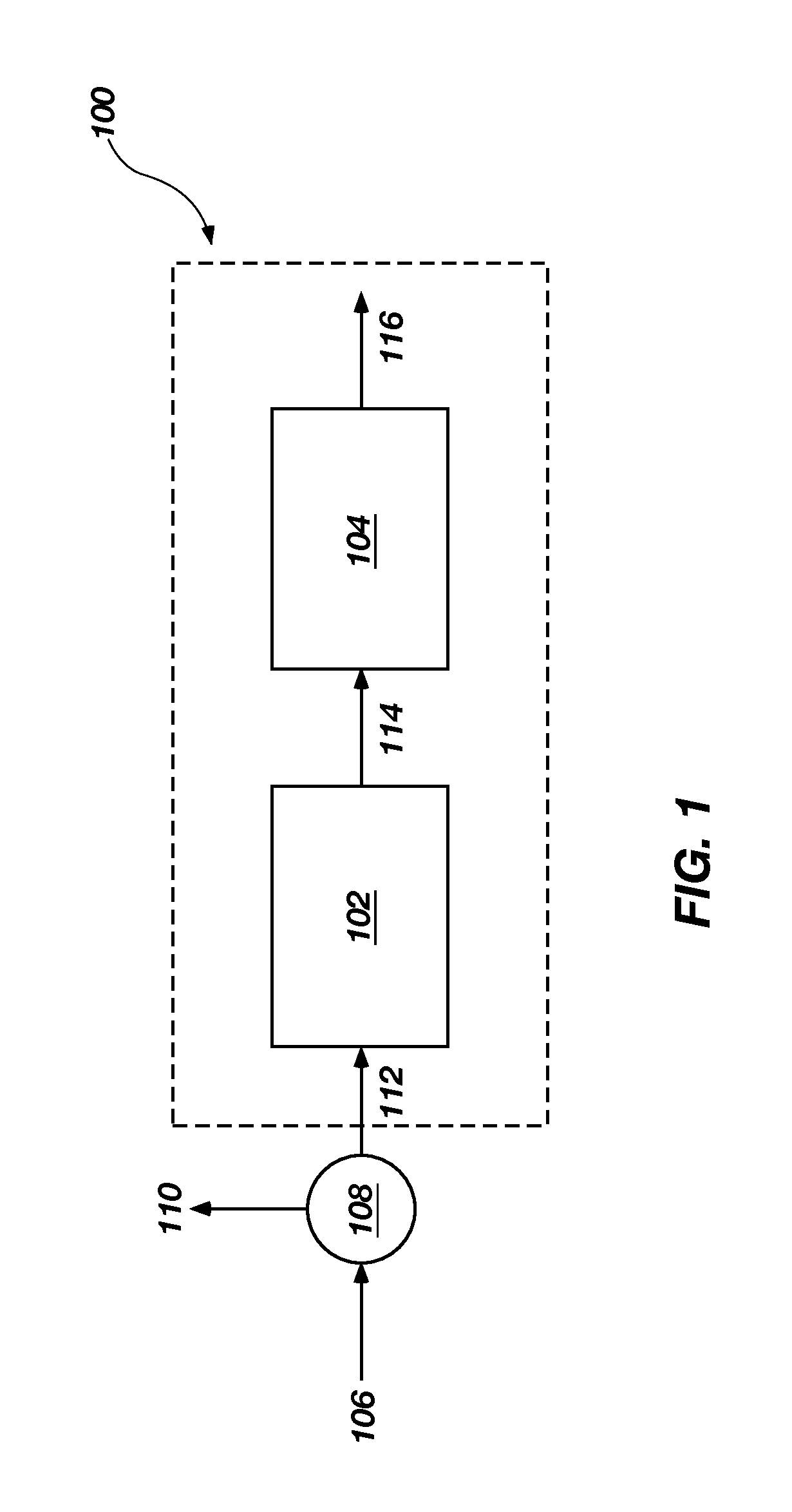
[0017]FIG. 1 illustrates a system 100 according to an embodiment of the present invention. It is noted that, while operation of embodiments of the present invention is described in terms of the sublimation of carbon dioxide in the processing of natural gas, the present invention may be utilized for the sublimation, heating, cooling, and mixing of other fluids and for other processes, as will be appreciated and understood by those of ordinary skill in the art.

[0018]The term “fluid” as used herein means any substance that may be caused to flow through a conduit and includes but is not limited to gases, two-phase gases, liquids, gels, plasmas, slurries, solid particles, and any c...


PUM


Abstract

A system for vaporizing and sublimating a slurry comprising a fluid including solid particles therein. The system includes a first heat exchanger configured to receive the fluid including solid particles and vaporize the fluid and a second heat exchanger configured to receive the vaporized fluid and solid particles and sublimate the solid particles. A method for vaporizing and sublimating a fluid including solid particles therein is also disclosed. The method includes feeding the fluid including solid particles to a first heat exchanger, vaporizing the fluid, feeding the vaporized fluid and solid particles to a second heat exchanger and sublimating the solid particles. In some embodiments the fluid including solid particles is liquid natural gas or methane including solid carbon dioxide particles.

Description

CROSS-REFERENCE TO RELATED APPLICATIONS[0001]The present application is related to co-pending U.S. patent application Ser. No. 11 / 855,071 filed on Sep. 13, 2007, titled HEAT EXCHANGER AND ASSOCIATED METHODS, U.S. patent application Ser. No. 12 / XXX,XXX filed on even date herewith and titled VAPORIZATION CHAMBERS AND ASSOCIATED METHODS (attorney docket number 2939-10080US (BA-494)) and copending U.S. patent application Ser. No. 12 / XXX,XXX filed on even date herewith and titled HEAT EXCHANGER AND RELATED METHODS (attorney docket number 2939-10081US(BA-495)). The disclosure of each of the foregoing applications is incorporated herein by reference in its entirety.CONTRACTUAL ORIGIN OF THE INVENTION[0002]This invention was made with government support under Contract Number DE-AC07-051D14517 awarded by the United States Department of Energy. The government has certain rights in the invention.FIELD OF THE INVENTION[0003]The invention relates generally to systems for vaporization and sublima...

Claims


Application Information

Patent Timeline
Patent Type & Authority Applications(United States)
IPC IPC(8): F25J3/08
CPCB01B1/005F25J1/0022F25J1/0027F25J3/061F25J3/067F25J3/08
Inventor TURNER, TERRY D.MCKELLAR, MICHAEL G.WILDING, BRUCE M.
Owner THE UNITED STATES AS REPRESENTED BY THE DEPARTMENT OF ENERGY
Why Eureka
Try Eureka