Auto-stereoscopic 3D display and display method thereof

Inactive Publication Date: 2012-05-03
AU OPTRONICS CORP
View PDF3 Cites 1 Cited by
  • Summary
  • Abstract
  • Description
  • Claims
  • Application Information

AI Technical Summary

Benefits of technology

[0021]As described above, constant opaque areas are produced along with the switching of a plurality of alternate vertical slits and vertical barriers provided by an LC scanning barrier. Thereby, not only the error tolerance of the attachment between the LC scanning barrier and an LCD is increased, but light leakage between any two adjacent areas (i.e., a transmissive slit and a non-transmissive barrier) of the LC scanning barrier is effectively prevented, so that the 3D image display quality of the LCD is ensured even when the LC scanning barrier cannot be perfectly attached to the LCD.

Problems solved by technology

However, in an LCD with the LC scanning barrier design, light leakage is likely to happen between the transmissive slit and non-transmissive barrier due to imperfect attachment between the LC scanning barrier and the LCD.
However, if the LC scanning barrier is imperfectly attached to the LCD (i.e., unaligned attachment), light leakage will happen at an area B between each pair of the transmissive slit and the non-transmissive barrier of the LC scanning barrier.
Thereby, the 3D image display quality of the LCD is greatly affected.

Method used


Image

  • Auto-stereoscopic 3D display and display method thereof
  • Auto-stereoscopic 3D display and display method thereof
  • Auto-stereoscopic 3D display and display method thereof

Examples


Embodiment Construction

[0029]Reference will now be made in detail to the present embodiments, examples of which are illustrated in the accompanying drawings. Wherever possible, the same reference numbers are used in the drawings and the description to refer to the same or like parts.

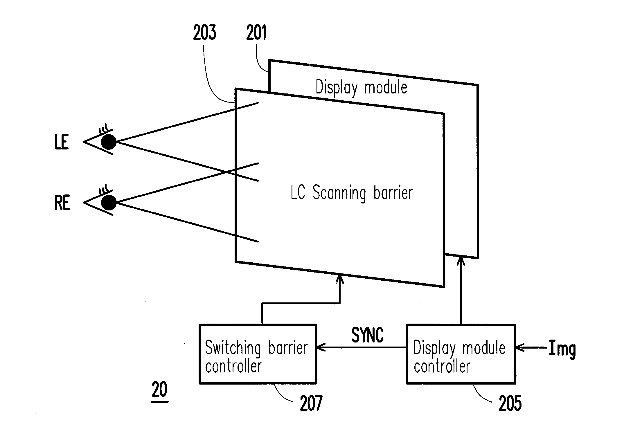
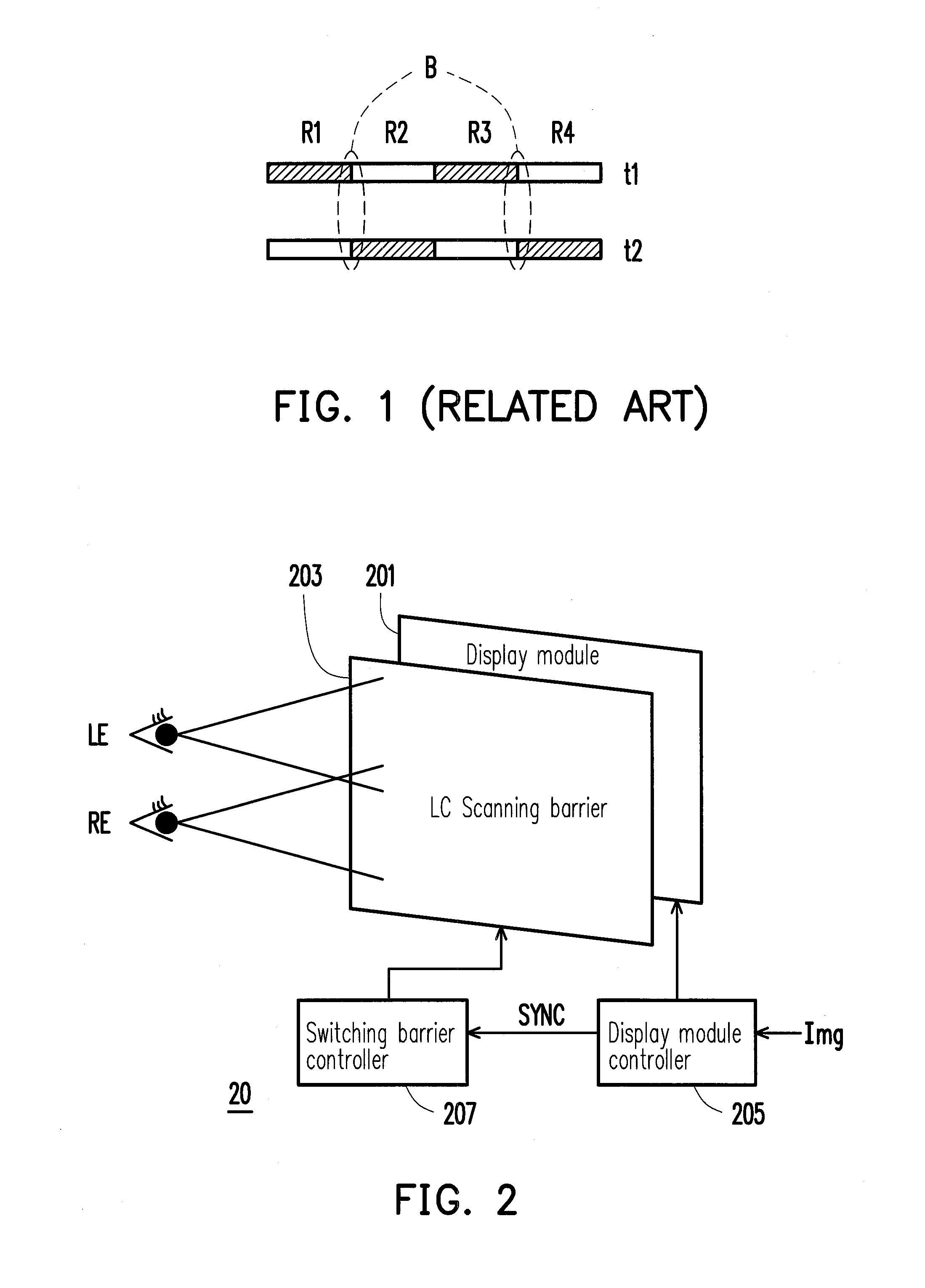
[0030]FIG. 2 is a diagram of an auto-stereoscopic 3D display 20 according to an embodiment. Referring to FIG. 2, the auto-stereoscopic 3D display 20 includes a display module 201 and a scanning barrier 203. The display module 201 may be a liquid crystal display (LCD) module or an organic light emitting diode (OLED) display module. Besides, the scanning barrier 203 may be a liquid crystal (LC) scanning barrier, and which will be referred to as an LC scanning barrier 203 thereinafter.

[0031]In the present embodiment, the display module 201 includes a display panel (not shown), a gate driving device (not shown), a source driving device (not shown), and a display module controller 205 (which may be a timing controller (T-con), not ...


PUM


Abstract

An auto-stereoscopic 3D display and a display method thereof are provided. The auto-stereoscopic 3D display includes a display module and a scanning barrier. The display module displays a 2D image. The scanning barrier is attached on the display module. The scanning barrier coordinates with the 2D image displayed by the display module to provide a switching of a plurality of alternate vertical slits and vertical barriers, so that a parallax is produced between a left eye and a right eye and accordingly a 3D image is sensed, wherein a constant opaque area exists between each of a pair of the slit and the barrier.

Description

CROSS-REFERENCE TO RELATED APPLICATION[0001]This application claims the priority benefit of Taiwan application serial no. 99136806, filed Oct. 27, 2010. The entirety of the above-mentioned patent application is hereby incorporated by reference herein and made a part of this specification.BACKGROUND[0002]1. Technical Field[0003]The disclosure generally relates to a 3D display technique, and more particularly, to an auto-stereoscopic 3D display and a display method thereof.[0004]2. Description of Related Art[0005]Parallax stereogram is a technique by which 3D images are presented to human eyes. In this technique, images presented to the left eye and the right eye are respectively cut along vertical pixel lines. Then, an integrated image is generated by re-arranging the cut images alternatively. When the integrated image is displayed, a parallax barrier is placed in front of the image so that the left eye image and the right eye image in the integrated image are respectively captured b...

Claims


Application Information

Patent Timeline
IPC IPC(8): G09G3/36G09G3/32G09G5/10
CPCG09G3/003G09G3/20H04N13/359H04N13/31H04N13/315G09G2300/023
Inventor LU, PEI-HUALIN, HONG-SHENWU, CHUN-WEICHANG, LEE-HSUN
Owner AU OPTRONICS CORP
Why Eureka
Try Eureka