Stone scanning device

A scanning equipment, stone technology, applied in image communication, electrical components and other directions, can solve the problems affecting the scanning system judgment, poor uniformity of light source, poor scanning accuracy, etc., to ensure scanning accuracy, good shielding effect, high absorption. Effect

Active Publication Date: 2022-01-21
泉州岩石智能科技有限公司
View PDF5 Cites 0 Cited by
  • Summary
  • Abstract
  • Description
  • Claims
  • Application Information

AI Technical Summary

Problems solved by technology

However, whether it is a single point light source or multiple point light sources, the uniformity of the light source is poor, and it is easy to affect the judgment of the scanning system.
Moreover, the traditional light source is usually set at the center of the scanning area, resulting in insufficient light in the edge area of ​​the stone slab, the scanning camera cannot capture the edge line of the stone slab, and the scanning accuracy is poor

Method used


Image

  • Stone scanning device
  • Stone scanning device
  • Stone scanning device

Examples


specific Embodiment

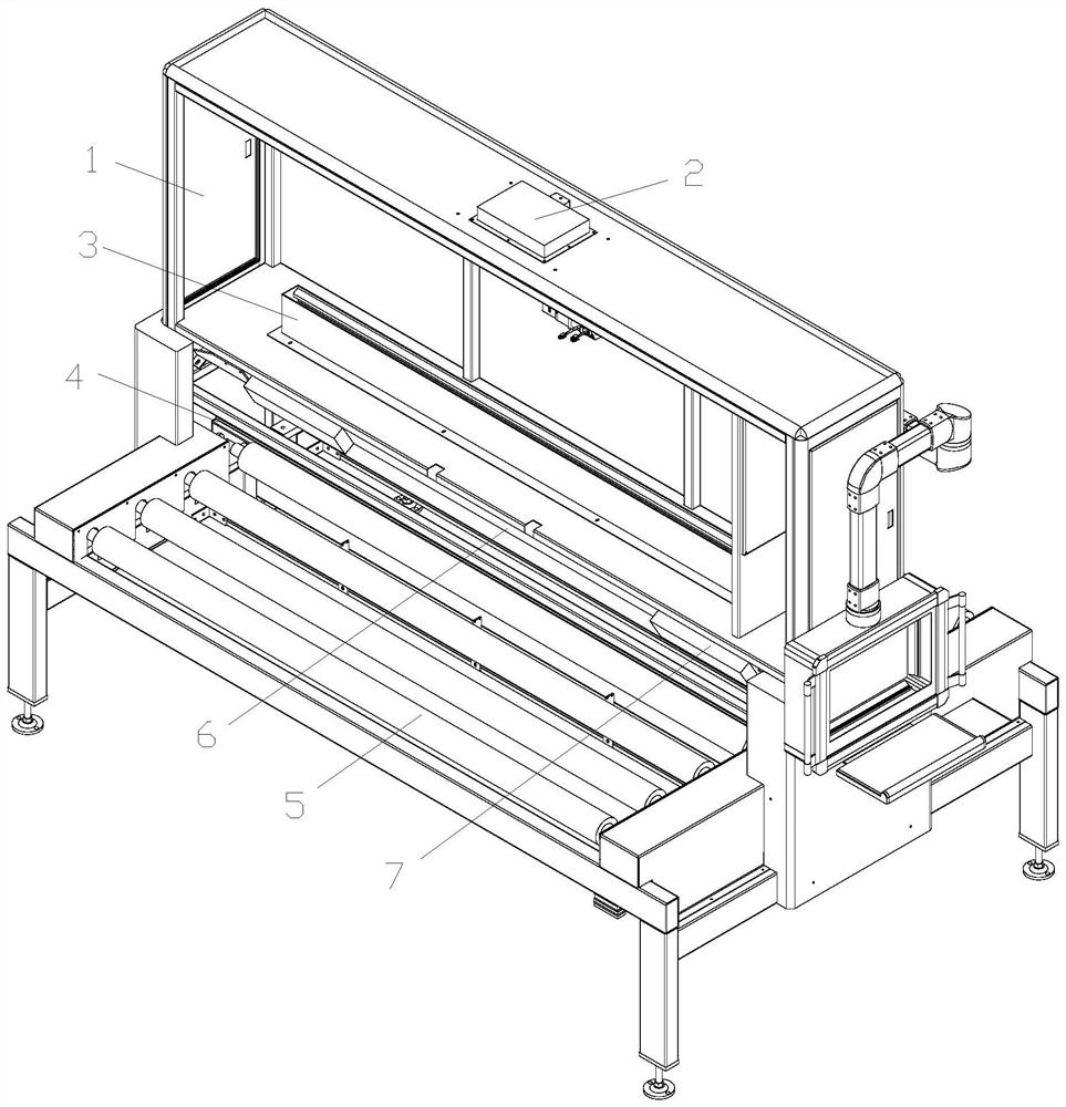
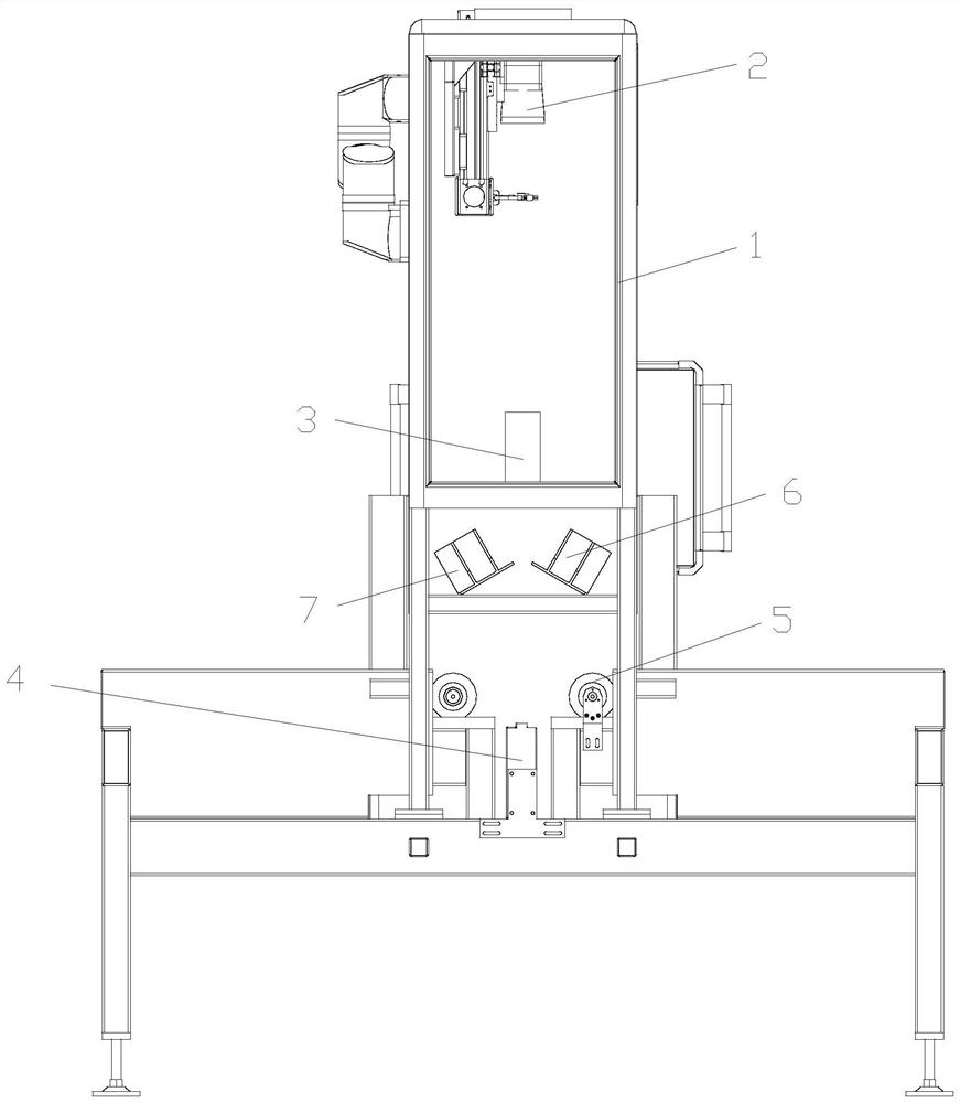
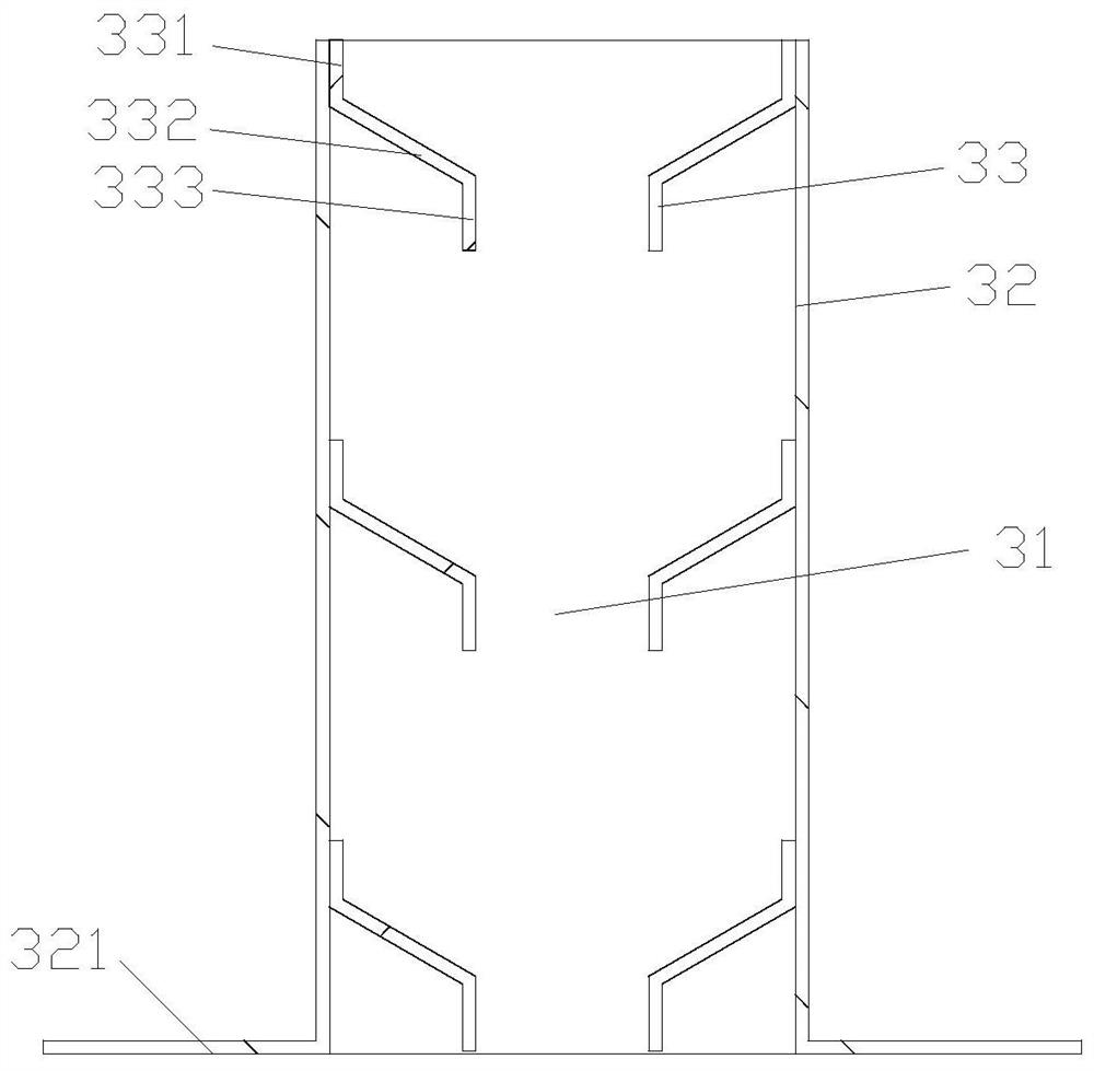
[0037] Specific examples: such as Figure 1-10 As shown, this embodiment provides a stone scanning device, which includes a frame on which a control panel is installed through a cantilever, and the frame is provided with a conveying mechanism 5 for transporting large stone slabs, a scanning mechanism for scanning stone Camera 2, a supplementary light mechanism for enhancing light and a shielding mechanism for shielding ambient light, the frame is provided with a sealed box 1 above the conveying mechanism 5, and the scanning camera 2 is arranged in the sealed box 1, The bottom of the sealed box 1 is provided with a through hole directly below the scanning camera 2. The shielding mechanism includes an upper shielding box 3 and a lower shielding box 4. The upper shielding box 3 is installed on the through hole, and the upper shielding box 3 The top is provided with an optical path through hole 31 for the scanning camera 2 to emit infrared rays downward and receive light signals. ...


PUM


Abstract

A stone scanning device provided by the present invention comprises a rack, the rack is provided with a conveying mechanism used for conveying a stone plate, a scanning camera used for scanning stone, a light supplementing mechanism used for enhancing light and a shielding mechanism used for shielding ambient light, and the rack is provided with a sealing box located above the conveying mechanism. The scanning camera is arranged in the sealing box, a through hole located under the scanning camera is formed in the bottom of the sealing box, the shielding mechanism comprises an upper shielding box and a lower shielding box, the upper shielding box is installed on the through hole, and a light path through hole used for the scanning camera to emit infrared rays downwards and receive light signals is formed in the upper shielding box. The top of the lower shielding box is provided with a light inlet hole used for absorbing ambient light. Ambient light can be effectively shielded, the linear light source is adopted, the light source uniformity is good, it can be guaranteed that the illumination intensity of the scanning edge area meets the scanning requirement, and therefore the scanning precision is guaranteed.

Description

technical field [0001] The invention relates to the technical field of scanning equipment, in particular to a stone scanning equipment. Background technique [0002] As a high-grade building decoration material, stone is widely used in indoor and outdoor decoration design, curtain wall decoration and public facilities construction. Stone is usually cut into a certain size before it is put into use. With the development of automatic stone cutting technology, automatic stone cutting can basically be realized, but due to the particularity of natural slabs, the specifications of each slab are different, so before cutting natural stone, it is necessary to scan the outline of the large stone slab , in order to cut according to the scan result. However, due to the large size of the stone slab, the light source will reflect at the edge of the stone slab and be collected by the scanning camera, and the existence of the ambient light signal will also interfere and weaken the signal, ...

Claims


Application Information

Patent Timeline
Patent Type & Authority Applications(China)
IPC IPC(8): H04N1/00H04N1/04
CPCH04N1/00519H04N1/04
Inventor 谭斌赖传宏徐杰
Owner 泉州岩石智能科技有限公司
Why Eureka
Try Eureka