5G optical fiber adapter for improving optical signal transmission

A fiber optic adapter and optical signal technology, applied in the coupling of optical waveguides, light guides, optics, etc., can solve problems such as light leakage, lack of blocking protection mechanism, and processing accuracy errors

Active Publication Date: 2022-03-22
ZHEJIANG CHAOQIAN TELECOMM TECH CO LTD
View PDF15 Cites 0 Cited by
  • Summary
  • Abstract
  • Description
  • Claims
  • Application Information

AI Technical Summary

Problems solved by technology

[0004] However, the current optical fiber adapter needs to be plugged and pulled out when in use, coupled with the error of processing accuracy, there must be a gap between the plug and the jack, and the plug and the jack are generally fixedly connected by buckles. In this way, when the plug is used for a long time and continuously plugged and pulled out, the gap between the plug and the jack will become larger and larger. If the gap between the plug and the jack is large and the vibration is large, the two optical fiber bodies will not be aligned. It is easy to cause light leakage, which leads to the loss of the signal of the fiber optic body. At the same time, the current fiber optic adapter lacks a blocking protection mechanism when it is not in use, so that the fiber optic adapter can prevent external dust and other impurities from invading the adapter when it is not inserted, thereby preventing the fiber optic adapter. Internal light channel components are affected or even damaged

Method used


Image

  • 5G optical fiber adapter for improving optical signal transmission
  • 5G optical fiber adapter for improving optical signal transmission
  • 5G optical fiber adapter for improving optical signal transmission

Examples


Embodiment Construction

[0028]The following will clearly and completely describe the technical solutions in the embodiments of the present invention with reference to the accompanying drawings in the embodiments of the present invention. Obviously, the described embodiments are only some of the embodiments of the present invention, not all of them. Based on the embodiments of the present invention, all other embodiments obtained by persons of ordinary skill in the art without making creative efforts belong to the protection scope of the present invention.

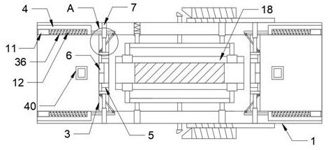
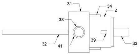
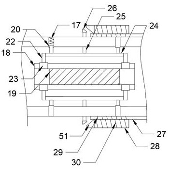
[0029] see Figure 1-7 , the present invention provides a technical solution: a 5G optical fiber adapter for improving optical signal transmission, the adapter includes a housing 1 and a connector 2, both sides of the housing 1 are fixed with partitions 3, the housing The upper and lower ends of both sides of the body 1 are provided with chute 4, and the inside of the partition plate 3 is provided with a blocking mechanism, and the blocking mechan...


PUM


Abstract

The invention discloses a 5G optical fiber adapter for improving optical signal transmission, the adapter comprises a shell and a connector, the two sides of the interior of the shell are fixedly provided with partition plates, the upper ends and the lower ends of the two sides of the interior of the shell are provided with sliding grooves, and the partition plates are internally provided with plugging mechanisms. And the plugging mechanism comprises a through groove, a plugging plate, a first telescopic rod, a connecting block, a first transmission block, a first rotating shaft, a sliding block, a connecting rod, a second transmission block, a second rotating shaft and a transmission rod, and the through groove is formed in the middle of the inner side of the partition plate. The optical fiber connector is good in use effect, can be automatically opened through the plugging mechanism when the connector is inserted into the housing, facilitates the connection of the optical fiber body, and can be automatically plugged when the connector is pulled out, thereby effectively preventing impurities from entering the housing, causing dust to enter the optical core assembly, and improving the reliability of the optical fiber connector. And the whole process is automatic without manual work, so that the situation of forgetting can be avoided.

Description

technical field [0001] The invention relates to the field of optical fiber adapters, in particular to a 5G optical fiber adapter that improves optical signal transmission. Background technique [0002] Optical fiber body is the abbreviation of optical fiber. It is a fiber made of glass or plastic and can be used as a light transmission tool. Usually, the transmitting device at one end of the fiber body uses a light-emitting diode or a beam of laser to transmit light pulses to the fiber body. The receiving device at the other end of the fiber body uses a photosensitive element to detect pulses. Since the loss of light in the optical fiber is much lower than that of electricity in the wire, the fiber body is used for long-distance information transmission. [0003] In the existing fiber optic body connection, fiber optic adapters are usually used to connect two fiber optic bodies with different interfaces. Fiber optic connectors are the most widely used optical passive compone...

Claims


Application Information

Patent Timeline
Patent Type & Authority Applications(China)
IPC IPC(8): G02B6/38
CPCG02B6/3807G02B6/3825G02B6/3849G02B6/3834G02B6/3823
Inventor 沈中山
Owner ZHEJIANG CHAOQIAN TELECOMM TECH CO LTD
Why Eureka
Try Eureka