
Wall mount hanger

a wall mount and hanger technology, applied in the direction of washstands, suspension devices, washstands, etc., to achieve the effect of reducing user inconvenience dramatically

Inactive Publication Date: 2012-05-10
CHENG CHENG GE
View PDF11 Cites 35 Cited by
  • Summary
  • Abstract
  • Description
  • Claims
  • Application Information

AI Technical Summary

Benefits of technology

[0011]Between contacting surfaces of the sleeve section and the hanging section, two arc surfaces are engaged with each other through the protruding teeth of the first and second arc surface, the sleeve section may use pitches of the protruding teeth as rotational pitch angle to rotate relative to the hanging section. In this way, even if deviation occurs when a user installs the hanging section and the sleeve section, the deviation can be adjusted through a relative rotation of the sleeve section and the hanging section, thus reducing user inconvenience dramatically.

Problems solved by technology

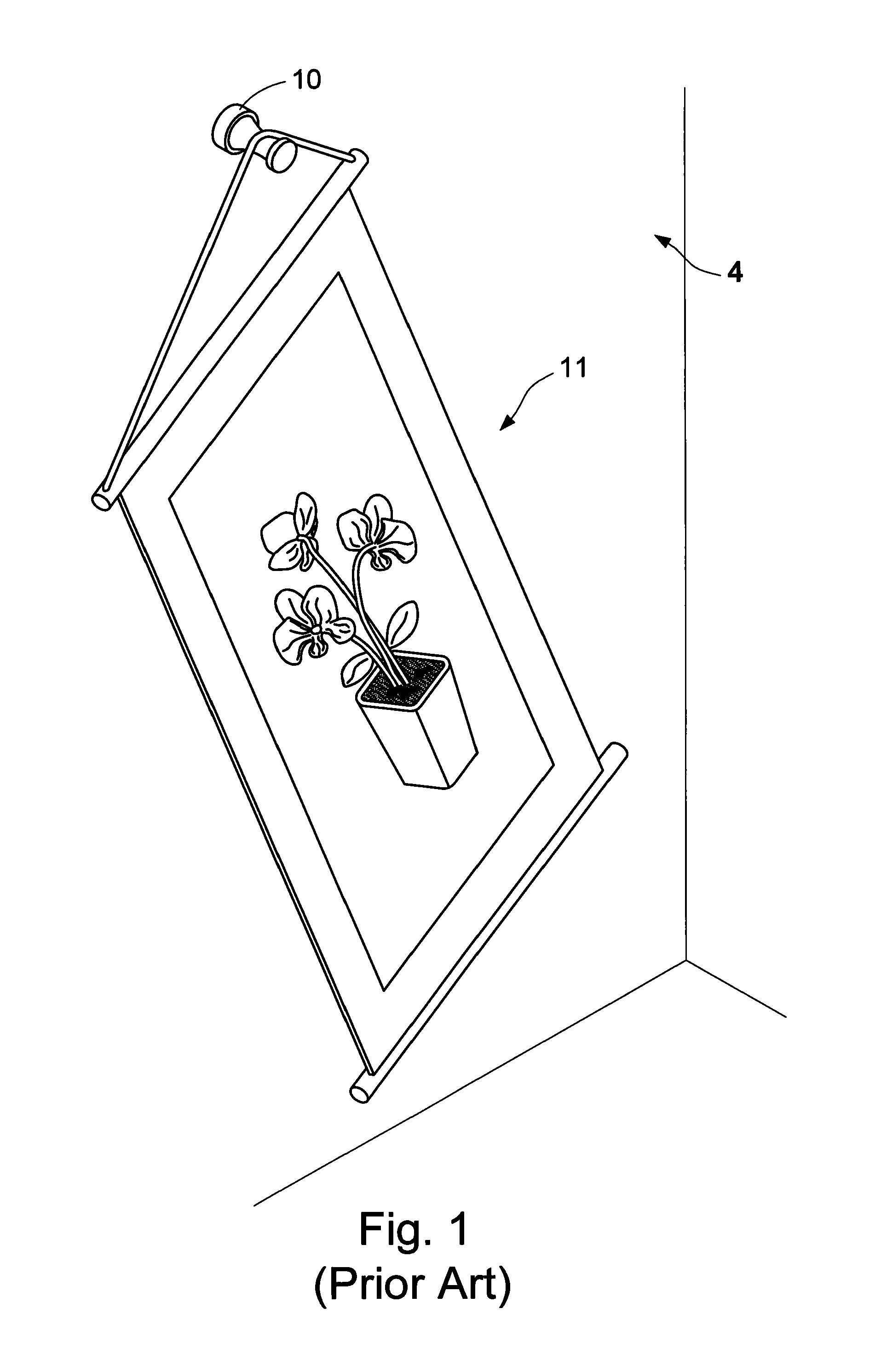
However, a user has to precisely measure when installing the hook; otherwise, the whole picture falls at an angle once the hook falls at an angle.

Method used


Image

  • Wall mount hanger
  • Wall mount hanger
  • Wall mount hanger

Examples


first embodiment

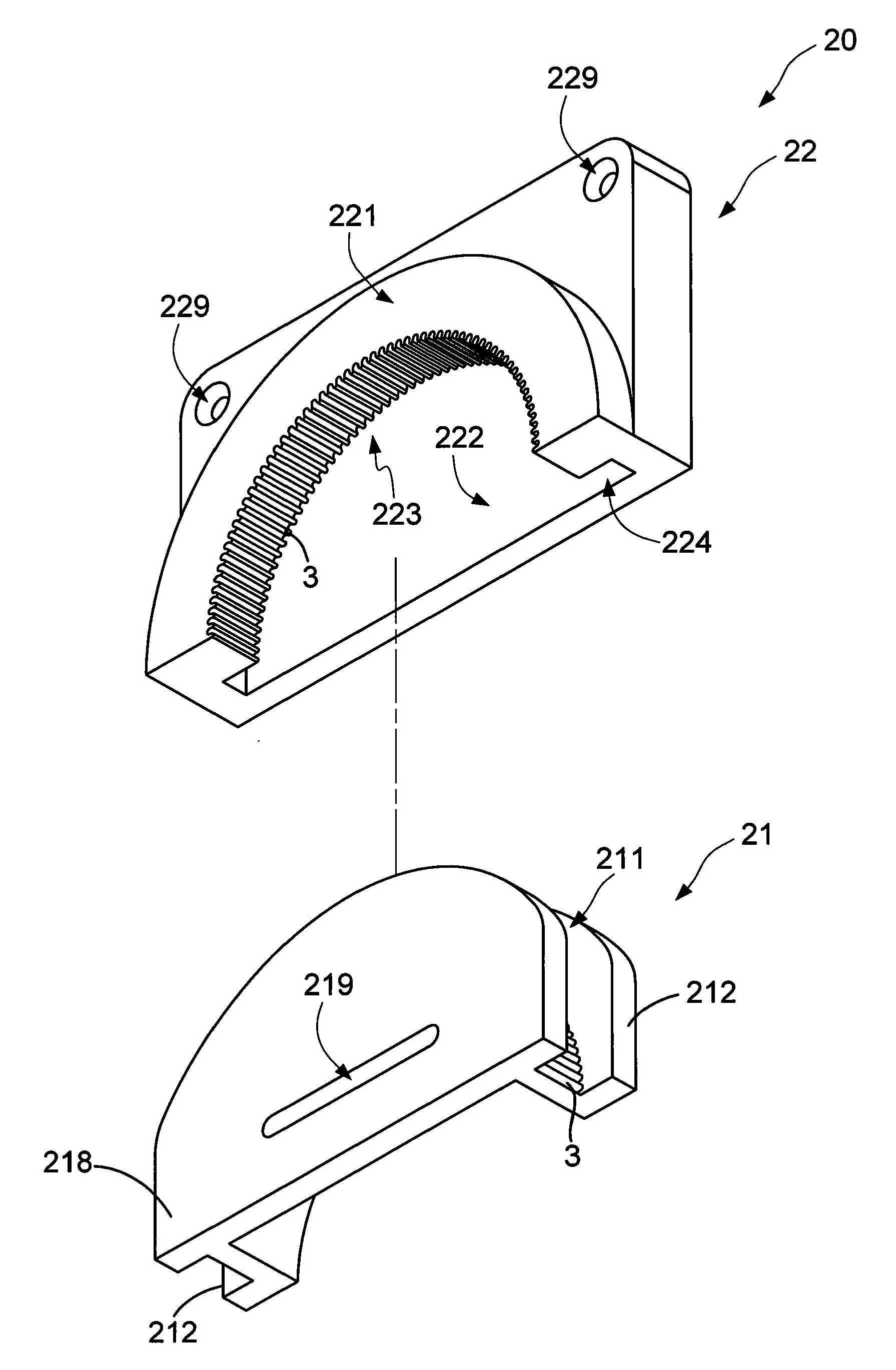
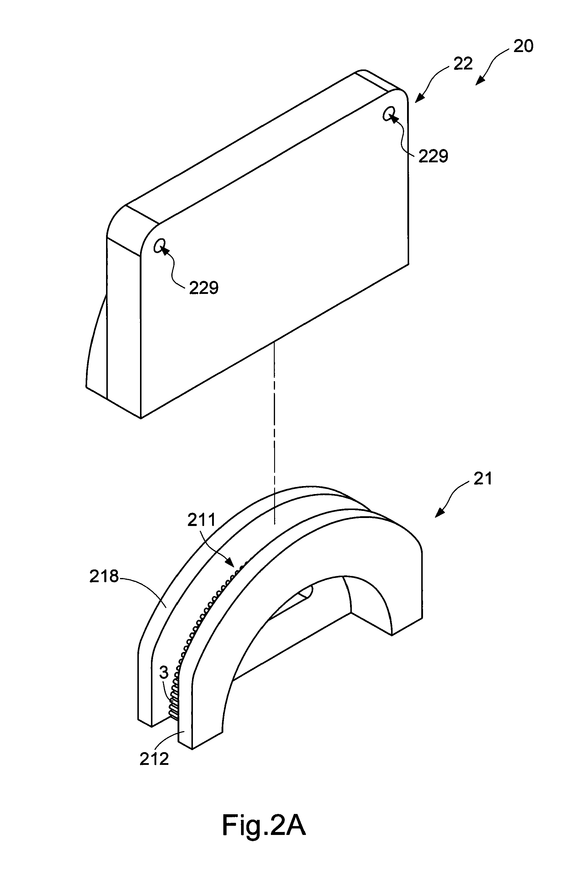
[0027]Please refer to FIGS. 2A to 3B, a wall mount hanger 20 according to the present invention includes a hanging section 21 and a sleeve section 22.

[0028]The hanging section 21 has a first arc surface 211 and a stop portion 212. The first arc surface 211 has a plurality of protruding teeth 3. The stop portion 212 is protrusively disposed on the first arc surface 211 and is higher than each of the protruding teeth 3. In the first embodiment, the hanging section 21 further includes a base 218, and is protrusively disposed on the wall surface 4 through a slotted hole 219 of the base 218, which is as shown in FIG. 4. In the first embodiment, another function of the slotted hole 219 lies in that a location for fixing the hanging section 21 can be fine-tuned in a left-right direction.

[0029]The sleeve section 22 has a first surface 221 and a second surface 222 lower than the first surface. Additionally, a second arc surface 223 and a slot 224 are disposed between the first surface 221 an...

second embodiment

[0033]FIG. 7 is a schematic view of the present invention. Please refer to FIG. 7, since a hole must be prepared on the wall surface 4 in the lock-fixing manner, if the location of the wall mount hanger 20 on the wall surface 4 is moved the user must prepare a hole again on the wall surface 4, and meanwhile try to cover the hole left in the original location. Therefore, in addition to the lock-fixing manner, in the present invention an adhesive on the back surface 5 may be disposed on the hanging section 21 and the sleeve section 22. Then the hanging section 21 is fixedly disposed on the wall 4 by adhesion, and the sleeve section 22 is fixedly disposed on the picture frame 111 by adhesion. The adhesive on the back surface 5 may be a double faced adhesive or other adhesives having an adhesion effect.

[0034]In addition, the wall mount hanger 20 of the present invention may be with different sizes or be of different materials to deal with various application conditions. For example, a m...


PUM


Abstract

A wall mount hanger includes a hanging section and a sleeve section. The hanging section is protrusively disposed on a wall surface and has a first arc surface and a stop portion. The first arc surface has plural protruding teeth, and the stop portion is protrusively disposed on the first arc surface. The sleeve section has a first surface and a second surface lower than the first surface. A second arc surface and a slot are disposed between the first surface and the second surface. The second arc surface has plural protruding teeth. The protruding teeth of the second arc surface are engaged with the protruding teeth of the first arc surface. Since the sleeve section and the hanging section are engaged with each other through the protruding teeth, the sleeve section can be rotated fixed to a required angle relative to the hanging section.

Description

CROSS-REFERENCES TO RELATED APPLICATIONS[0001]This non-provisional application claims priority under 35 U.S.C. §119(a) on Patent Application No. 99215395 filed in Taiwan, R.O.C. on Aug. 11, 2010, the entire contents of which are hereby incorporated by reference.BACKGROUND OF THE INVENTION[0002]1. Technical Field[0003]The present invention relates to a wall mount hanger, and more particularly to a wall mount hanger having an arc surface equipped with anti-slip mechanism.[0004]2. Related Art[0005]A wall mount hanger is a common accessory in daily life. Usually, the wall mount hanger is used to hang clothes and hats, keys, necklaces, calligraphic works and paintings, posters, and potted plants. A common wall mount hanger is a hook disposed on a wall surface, and objects are hung on the hook. Sometimes, the wall mount hanger is a rod directly protruding on the wall surface, and objects are hung on the protruding portion of the rod. Sometimes, a wall mount hanger of universal specificati...

Claims


Application Information

Patent Timeline
IPC IPC(8): F16B47/00F16M13/02
CPCA47G7/044A47G25/02A47G1/1613A47G29/10A47G25/10
Inventor CHENG, CHENG-GE
Owner CHENG CHENG GE
Learn More