Method and means of lining a manhole

a manhole and liner technology, applied in the field of manhole repair, can solve the problems of many manholes made long ago, many manholes have begun to deteriorate or damage areas, eventual collapse of manholes, etc., and achieve the effect of reducing rips and/or tears in the liner

Inactive Publication Date: 2012-05-10
LMK TECH LLC
View PDF7 Cites 7 Cited by
  • Summary
  • Abstract
  • Description
  • Claims
  • Application Information

AI Technical Summary

Benefits of technology

[0006]It is therefore a principal object, feature, or advantage of the present invention to provide an improved method and means for lining a wall of a manhole which improves over or solves the problems and deficiencies in the art.
[0007]Another object, feature, or advantage of the present invention is to provide an improved means and method to line a manhole wall with a liner so that the liner does not rip or tear during lining.
[0008]Another object, feature, or advantage of the present invention is to provide an improved method and means of lining a manhole having various sizes.
[0009]Another object, feature, or advantage of the present invention is to provide a method and means to line a manhole from the top of the manhole downwardly to reduce rips and / or tears in the liner.
[0010]Another object, feature, or advantage of the present invention is to provide a method and means for lining a manhole of various sizes from the bottom of the manhole upwardly to reduce rips and / or tears in the liner.

Problems solved by technology

One problem with existing manholes is that many were made long ago, and then oftentimes were made of brick.
Due to the old age of the manholes, as well as the materials used to make them, many manholes have begun to deteriorate or have damaged areas.
The damaged areas create weak spots, which may allow water to infiltrate the sewer system and also lead to the eventual collapse of the manhole.
One problem with this method is that the liner must stretch circumferentially as the bladder expands.
Therefore, when the top portion of the liner stretches circumferentially, it does not have the requisite material to take from to account for the larger circumference.
Because the liner is anchored at the casting and at the midpoint along the wall of the manhole, this may cause the liner to rip or not fit tightly against the manhole wall to properly repair the wall.
Also, this same problem occurs to non-stretching liners, as the length of the liner must be increased as the bladder expands, pressing the liner against the manhole wall.

Method used


Image

  • Method and means of lining a manhole
  • Method and means of lining a manhole
  • Method and means of lining a manhole

Examples


Embodiment Construction

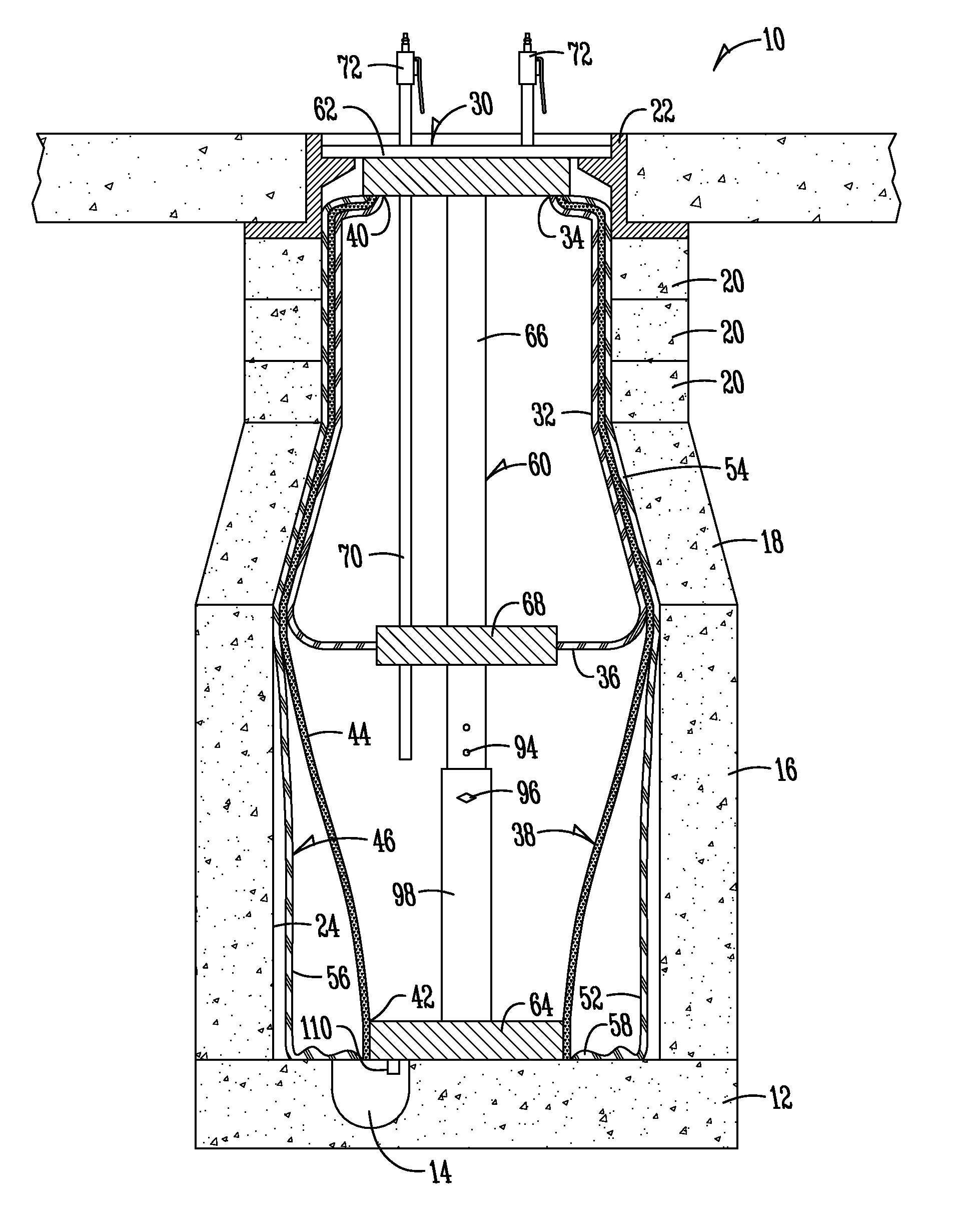
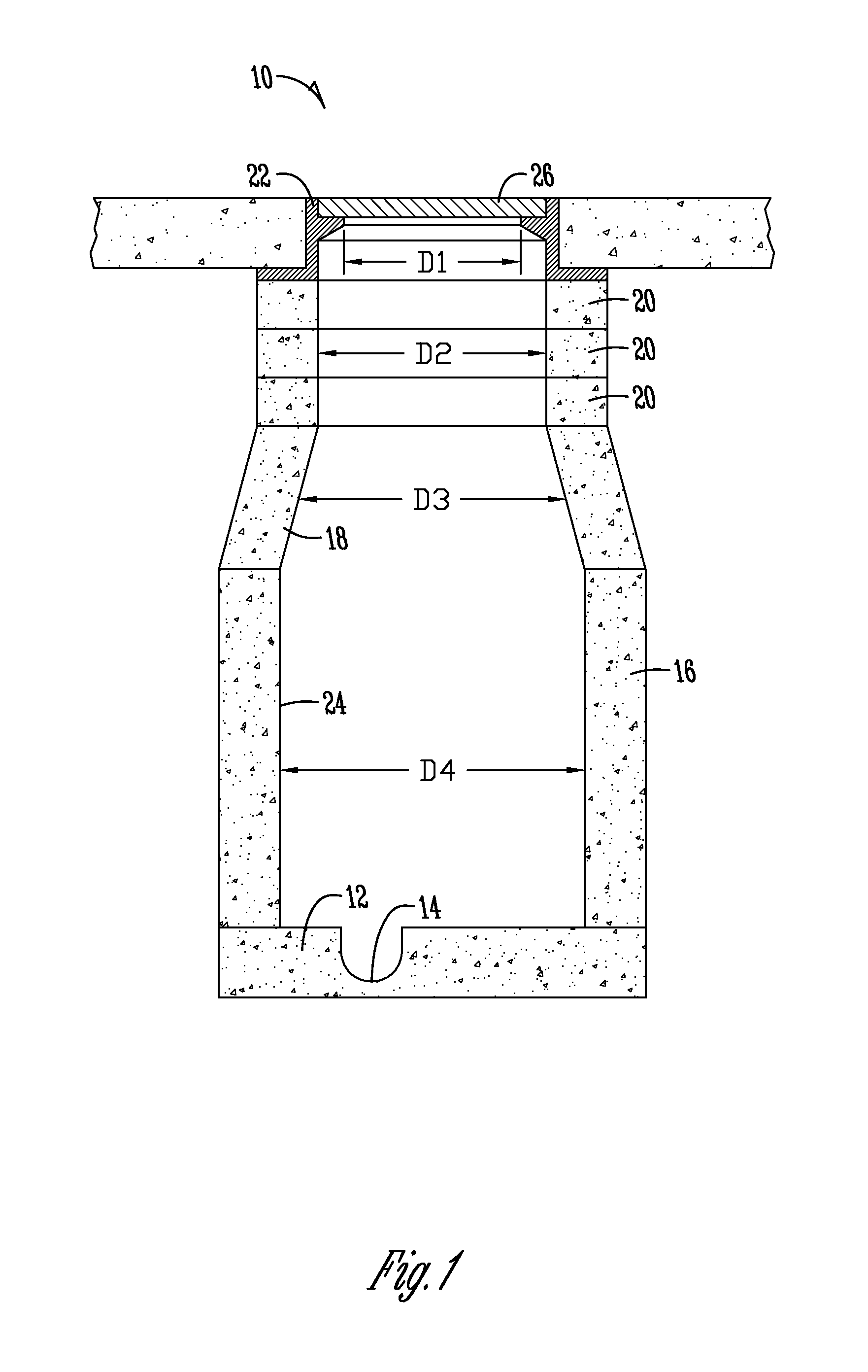
[0032]A typical manhole 10 has a floor 12 that includes a run through 14. The floor 12 is attached to a barrel 16, a cone section 18, and a plurality of adjusting rings 20. A casting frame 22 is mounted at the upper end of the manhole 10. On top of the casting frame 22 sits a lid 26. As shown in FIG. 1, the manhole 10 includes a number of diameters D1, D2, D3 and D4. While all manholes generally have areas of different diameters, the exact shape and size of the manholes will vary. For example, FIG. 1 shows a manhole 10 having a concentric cone section, but other manholes may have eccentric cone sections. A manhole wall 24 may be formed of brick, and the bricks may become spaced apart from one another. This may cause defects and cracks in the wall 24 of the manhole 10, which necessitate repair. The repair may be needed along the entire wall 24 of the manhole 10, or in a more localized spot. However, it is generally desired to repair the wall 24 of the manhole 10 from the floor 12 up ...


PUM

PropertyMeasurementUnit
diameteraaaaaaaaaa
lengthaaaaaaaaaa
thicknessaaaaaaaaaa

Abstract

An apparatus and method is provided for lining the wall of a manhole. The apparatus may include a liner assembly, which includes an expansion device, an auxiliary bladder, a primary bladder, and a liner. The auxiliary bladder is first inflated near the top of the manhole. Next the primary bladder may be expanded to press the liner against the wall of the manhole. The liner, being impregnated with a resinous material, is pressed against the wall until the resinous material cures and hardens. The expansion device, auxiliary bladder, and primary bladder are then removed from the manhole. The result is a repaired manhole wall.

Description

FIELD OF THE INVENTION[0001]The present invention relates generally to a method and means for repairing a manhole. More particularly, but not exclusively, it relates to a method and assembly for lining a manhole wall.BACKGROUND OF THE INVENTION[0002]Conventional manholes include a lower or bottom pad, a barrel having a relatively constant diameter adjacent the pad, a concentric or eccentric cone extending upwardly from the barrel, one or more adjusting rings to adjust the overall height of the manhole, and a casting frame on top of the adjusting rings to support a lid at an elevation substantially level with the surrounding pavement. The casting frame is preferably sealed to the uppermost adjusting ring to preclude or minimize water flow into the manhole.[0003]One problem with existing manholes is that many were made long ago, and then oftentimes were made of brick. Due to the old age of the manholes, as well as the materials used to make them, many manholes have begun to deteriorat...

Claims


Application Information

Patent Timeline
Patent Type & Authority Applications(United States)
IPC IPC(8): B29C63/20E04B1/66
CPCB29C63/34E02D29/128E02D29/12E02D29/125E02D2300/0006E02D2450/10E02D2450/106
Inventor KIEST, JR., LARRY W.MATHEY, JASON M.
Owner LMK TECH LLC
Why Eureka
Try Eureka