Filter circuit, duplexer and RF module
- Summary
- Abstract
- Description
- Claims
- Application Information
AI Technical Summary
Problems solved by technology
Method used
Image

Examples
Example
First Embodiment
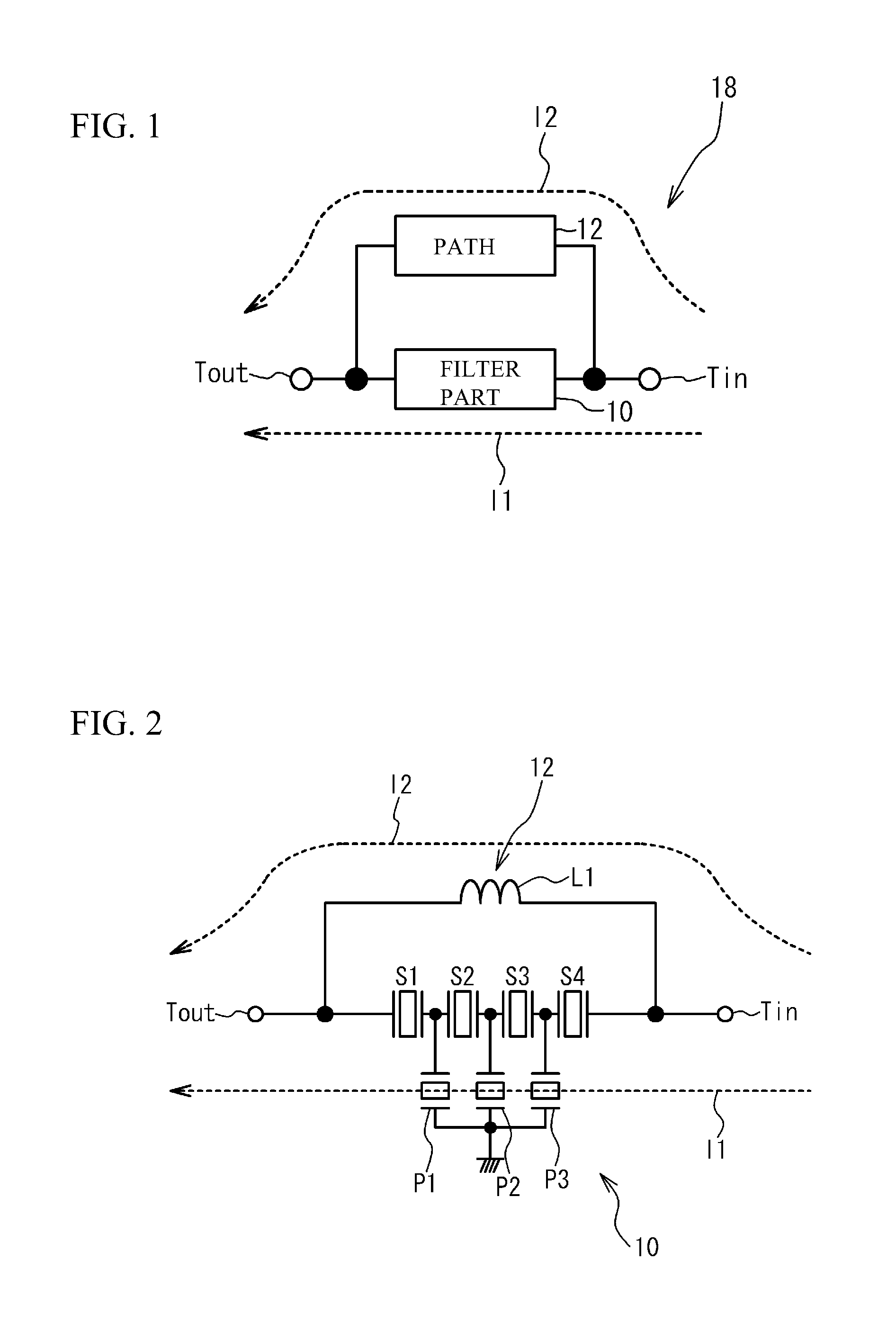
[0031]FIG. 1 is a circuit diagram of a filter circuit in accordance with a first embodiment.
[0032]Referring to FIG. 1, a filter circuit 18 is composed of a filter part 10 and a path 12. The filter part 10 is connected between an input terminal Tin and an output terminal Tout. The path 12 is connected in parallel with the filter part 10 between the input terminal Tin and the output terminal Tout. An input signal passing through the input terminal Tin is applied to the filter part 10 and the path 12. A signal I1 that passes through the filter part 10 and a signal I2 that passes through the path 12 are combined with each other and are then output via the output terminal Tout. The filter part 10 is a bandpass filter having a passband. The filter part 10 passes signals in the passband and attenuates signals outside of the passband.
[0033]The impedance of the path 12 is selected as follows. The first signal I1 and the second signal I2 have an opposite phase relationship at ...
Example
Second Embodiment
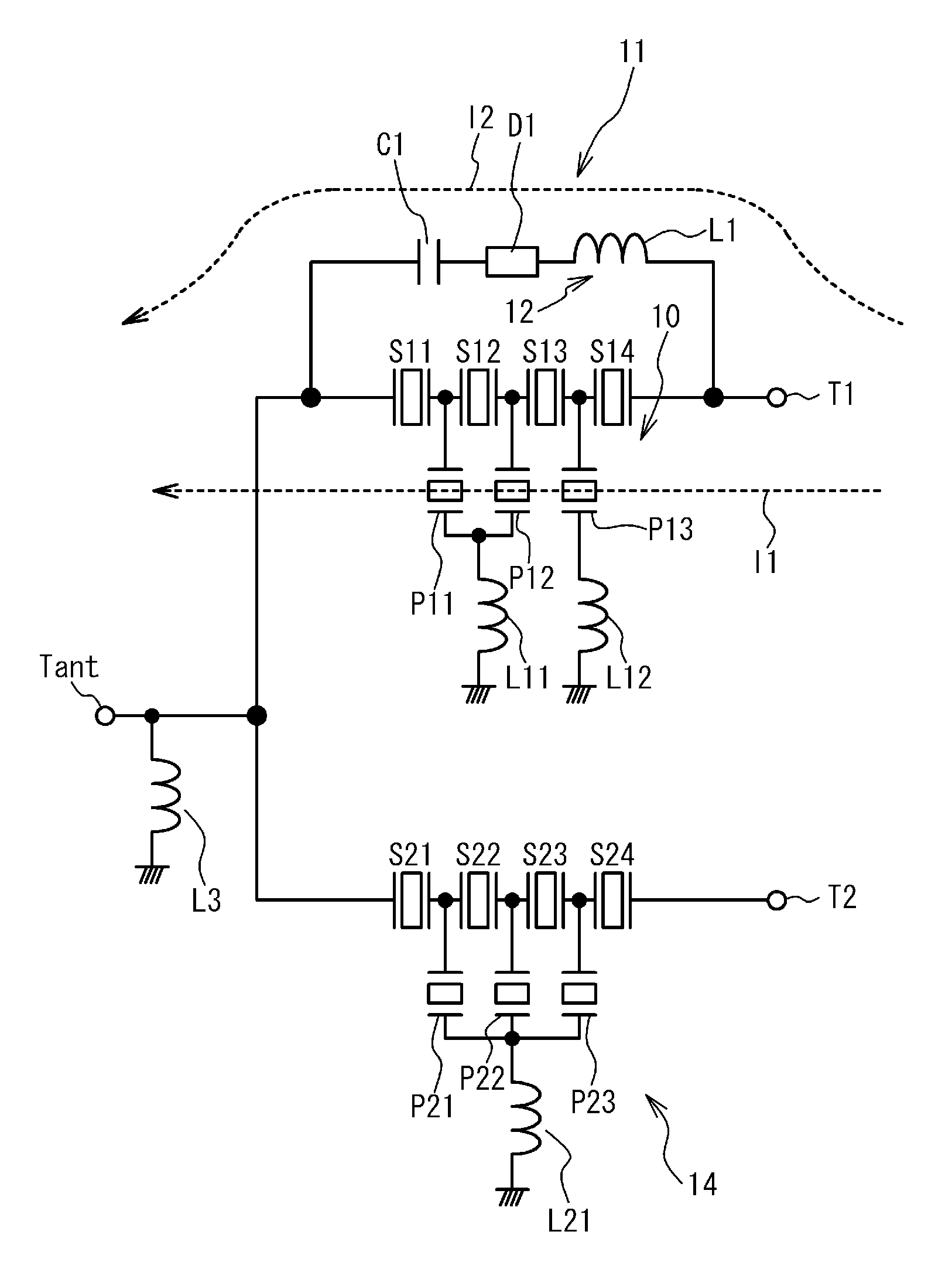
[0037]A second embodiment has an exemplary structure in which the path 12 includes an inductor. FIG. 2 is a circuit diagram of a filter circuit according to the second embodiment. The filter part 10 has a ladder type filter. The path 12 includes an inductor L1 having two ends. One of the two ends is connected to the input terminal Tin and the other end is connected to the output terminal Tout. The filter part 10 includes one or multiple series resonators S1˜S4 and one or multiple parallel resonators P1˜P3. The series resonators S1˜S4 are connected in series between the input terminal Tin and the output terminal Tout. The parallel resonators P1˜P3 are connected in parallel between the input terminal Tin and the output terminal Tout.
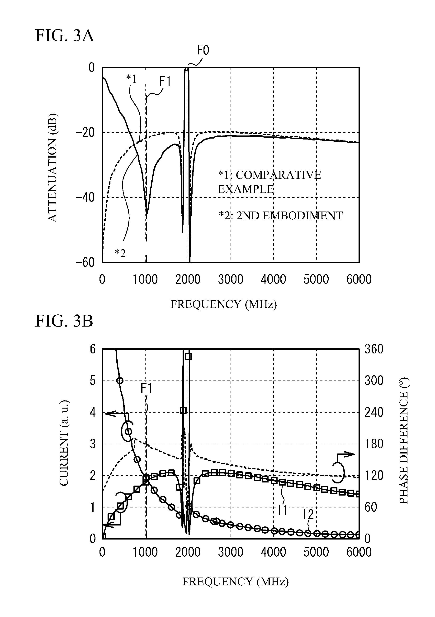
[0038]A simulation was conducted in which the inductance of the inductor L1 was set to 150 nH and the filter part 10 was a ladder type filter. The ladder type filter had a six-stage configuration and had surface acoustic wave resonators us...
Example
Third Embodiment
[0042]A third embodiment has an exemplary configuration in which the path 12 is composed of an inductor and a capacitor. FIG. 4 is a circuit diagram of a filter circuit according to the third embodiment. As compared with FIG. 2 of the second embodiment, the path 12 includes a capacitor C1 connected in series to the inductor L1, and the LC circuit thus configured is connected between the input terminal Tin and the output terminal Tout. The other structures of the third embodiment are the same as those of the second embodiment illustrated in FIG. 2, and a description thereof is omitted here. A simulation was conducted in which the inductance of the inductor L1 was set to 250 nH and the capacitance of the capacitor C1 was set to 0.2 pF. The other conditions are the same as those of the simulation of the second embodiment.
[0043]FIG. 5A illustrates a passband characteristic of the filter circuit of the third embodiment, and FIG. 5B illustrates currents of signals and phas...
PUM
 Abstract
Description
Claims
Application Information
 - R&D Engineer
- R&D Manager
- IP Professional
- Industry Leading Data Capabilities
- Powerful AI technology
- Patent DNA Extraction
Browse by: Latest US Patents, China's latest patents, Technical Efficacy Thesaurus, Application Domain, Technology Topic.
© 2024 PatSnap. All rights reserved.Legal|Privacy policy|Modern Slavery Act Transparency Statement|Sitemap