Circuit breaker with controlled exhaust

a circuit breaker and exhaust technology, applied in the direction of protective switch details, non-enclosed substations, substations, etc., can solve the problems of internal pressure generation, and achieve the effect of allowing more time for the gas to cool, and minimizing or reducing the discoloration and/or scorching of the pain

Active Publication Date: 2012-05-17
SCHNEIDER ELECTRIC USA INC
View PDF4 Cites 28 Cited by
  • Summary
  • Abstract
  • Description
  • Claims
  • Application Information

AI Technical Summary

Benefits of technology

[0003]The present invention couples a chamber including one or more baffles to a housing of a circuit breaker near an exit of a vent channel of the circuit breaker to provide an additional volume and length of the vent channel for produced gas and debris to travel prior to being expelled into an electrical enclosure. Such an additional volume provides more time for the gas to cool and provides more space to trap some of the debris the...

Problems solved by technology

But these obstructions increase the internal pressure generated during the circuit interruption, which can be undesirable.
Additionally, some circuit breaker vents allow the generate...

Method used


Image

  • Circuit breaker with controlled exhaust
  • Circuit breaker with controlled exhaust
  • Circuit breaker with controlled exhaust

Examples


Embodiment Construction

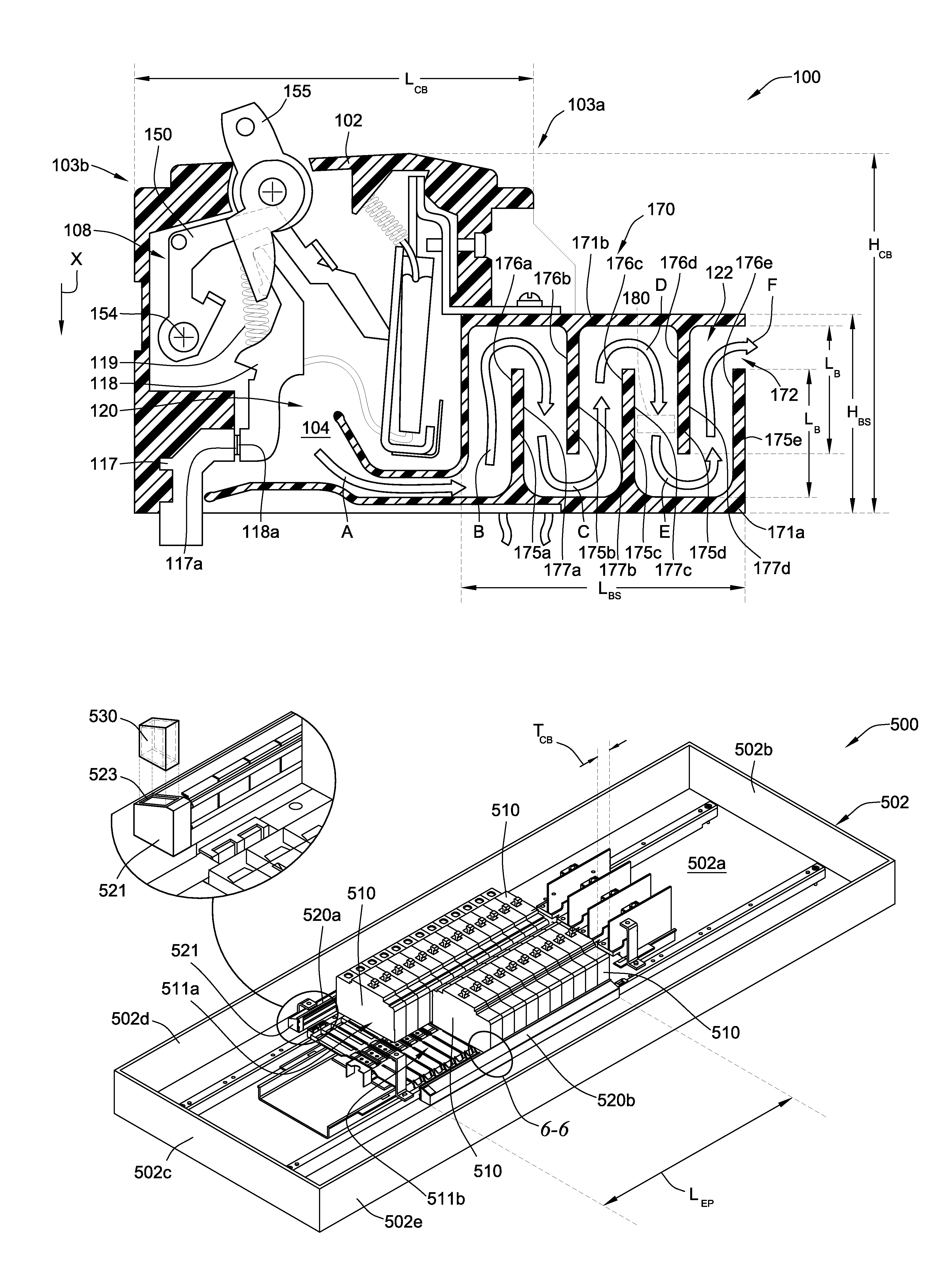
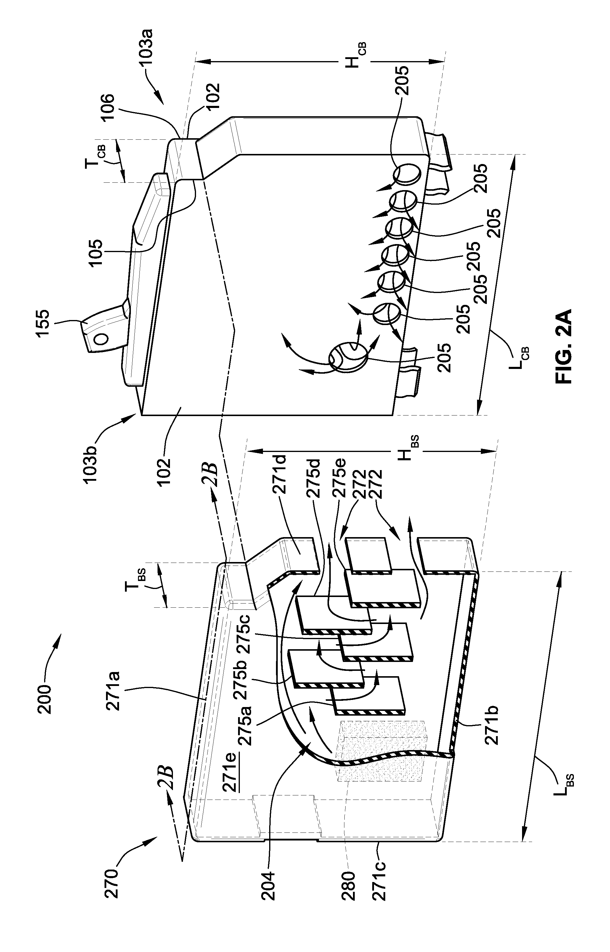
[0015]FIG. 1 is a cross-sectional view of a circuit breaker assembly 100 having a chamber 170 that receives and directs some of the gas and debris produced during a circuit interruption. The circuit breaker assembly 100 includes a housing 102, preferably composed of a molded plastic, that houses the various working components of the circuit breaker assembly 100. The chamber 170 is also preferably composed of a molded plastic, although other materials are contemplated. Conventionally, the circuit breaker assembly 100 includes a trip mechanism 108 that causes a movable contact 118a to separate from a stationary contact 117a in response to detection by the circuit breaker assembly 100 of an electrical fault. Some components of the traditional circuit breaker components are omitted or not described, however, these components, which may be found in, for example, the SQUARE D® miniature circuit breakers available from Schneider Electric, are not necessary for an understanding of aspects o...


PUM


Abstract

A circuit breaker assembly includes a housing, a trip mechanism, a vent channel, and a chamber. The trip mechanism is positioned within the housing can causes a movable contact to separate from a second contact in response to detection by the circuit breaker assembly of an electrical fault. The vent channel is formed in the housing and positioned to exhaust gas and debris produced as the movable contact separates from the second contact during the electrical fault to an aperture in the housing. The chamber has a chamber housing coupled to the housing adjacent the aperture such that the chamber receives the gas and debris exiting the aperture.

Description

FIELD OF THE INVENTION[0001]The present disclosure relates to circuit breaker assemblies, and, more particularly, to circuit breaker assemblies including a chamber for cooling and collecting gas and debris produced during a circuit interruption.BACKGROUND[0002]Vents relieve pressure in circuit breakers generated by ionized gas produced during a circuit interruption and can be situated near grounded metal that is part of the circuit-breaker enclosure or near a line-side bus, which is at a different voltage than the exiting gas. Vents also guide the debris and gas along a path so that they can be exhausted safely away from the circuit breaker. Debris generated during the circuit interruption can include metal particles that can be made molten by hot ionized gas. When the debris exits the circuit breaker, it can reduce the dielectric strength of the vent path and the through-air and over-surface dielectric spacings to grounded metal or bussing just outside the vent and promote a ground...

Claims


Application Information

Patent Timeline
IPC IPC(8): H02B7/00H01H33/08
CPCH01H71/025H01H9/342H01H71/522
Inventor RAABE, RODNEY D.BARENZ, DAVID W.BROGHAMMER, WILLIAM J.
Owner SCHNEIDER ELECTRIC USA INC
Why Eureka
Try Eureka