Method and system for controlling medical monitoring equipment

a monitoring equipment and user interface technology, applied in the field of medical monitoring equipment, can solve the problems of patient may be spontaneously trying to breathe but not being able to complete a full respiratory cycle, and not being able to provide all such information in a single gui setting,

Inactive Publication Date: 2012-05-17
GENERAL ELECTRIC CO
View PDF2 Cites 37 Cited by
  • Summary
  • Abstract
  • Description
  • Claims
  • Application Information

AI Technical Summary

Problems solved by technology

These respiratory difficulties may be pathological in nature or may be due to the fact that the patient is too weak or sedated to independently perform respiration functions.
Often, the patient may be spontaneously attempting to breathe but is not able to complete a full respiratory cycle.
However, it is often not feasible to provide all such information in a single GUI setting because of the different types of personnel who may interact with the patient.
Accordingly, the available information may be presented in a fashion that is therefore not optimized for any user, or displayed information may be optimized for a single user which then is non-optimal for other users.

Method used


Image

  • Method and system for controlling medical monitoring equipment
  • Method and system for controlling medical monitoring equipment
  • Method and system for controlling medical monitoring equipment

Examples


Embodiment Construction

[0020]The operating environment of the invention is described with respect to a bedside ventilator unit. However, it will be appreciated by those skilled in the art that the invention is equally applicable for use with any hospital monitoring equipment such as anesthesia machines and vital signs monitoring equipment that may be controlled by a computer having interaction via a touchscreen monitor or a graphical user interface (GUI).

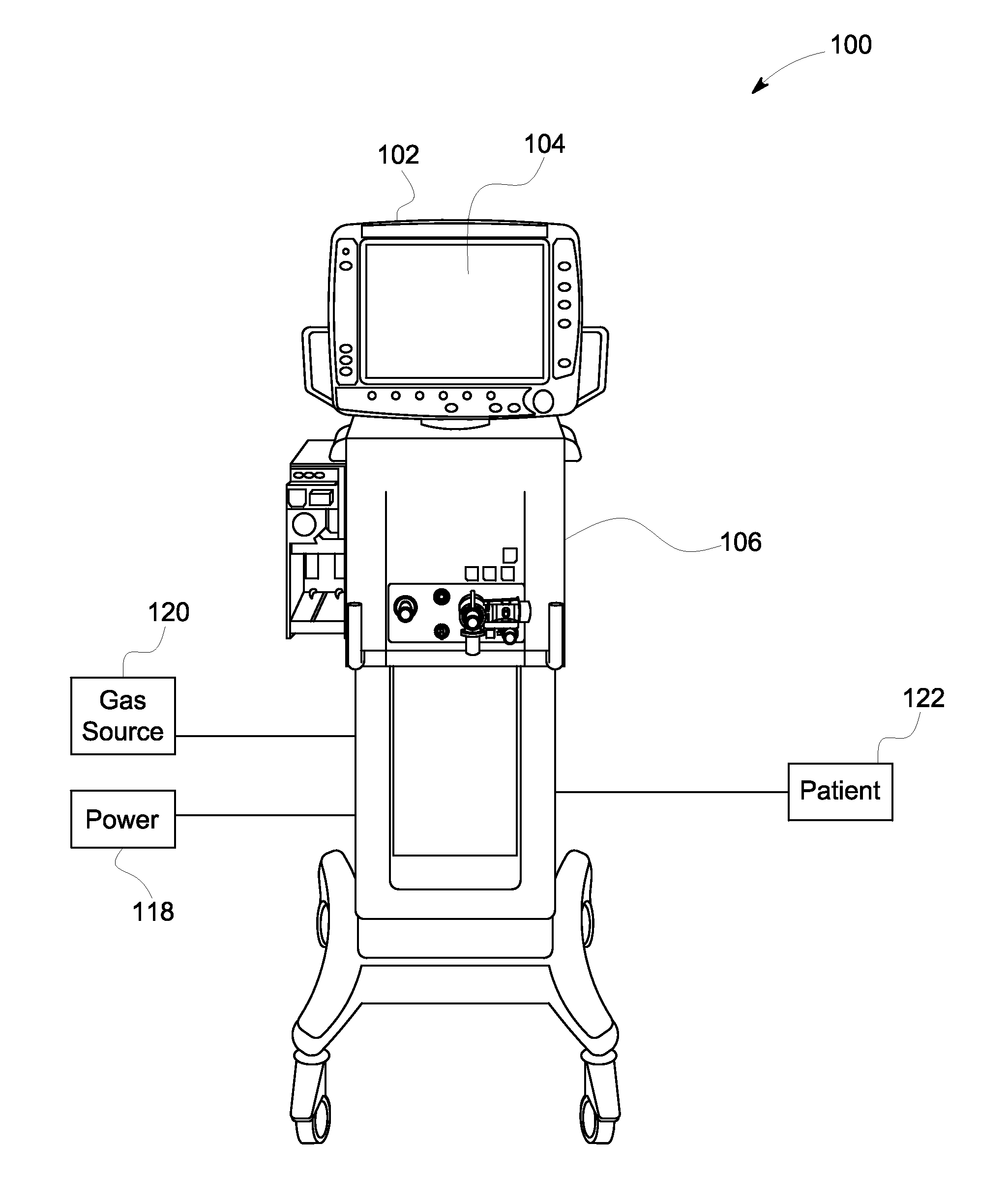
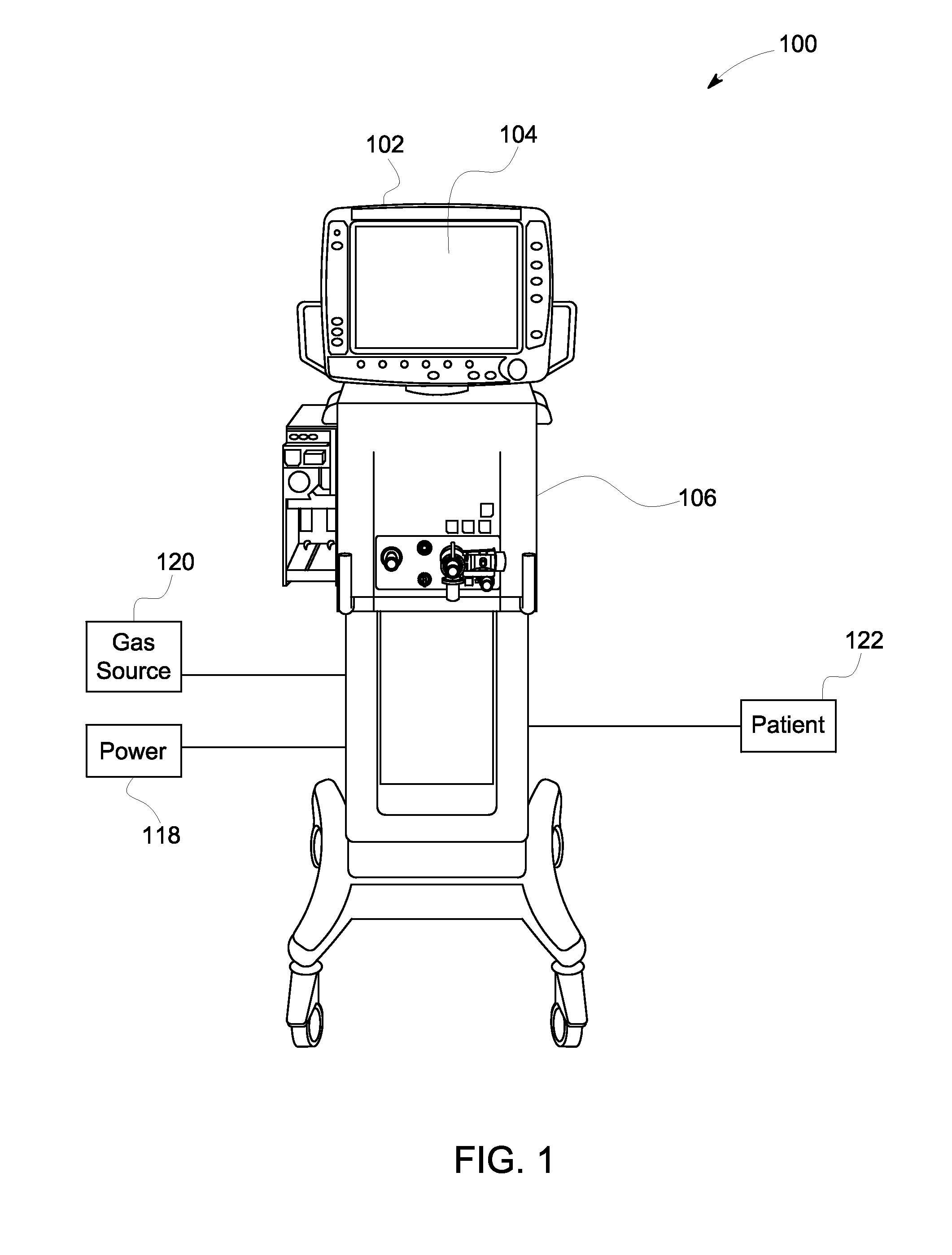
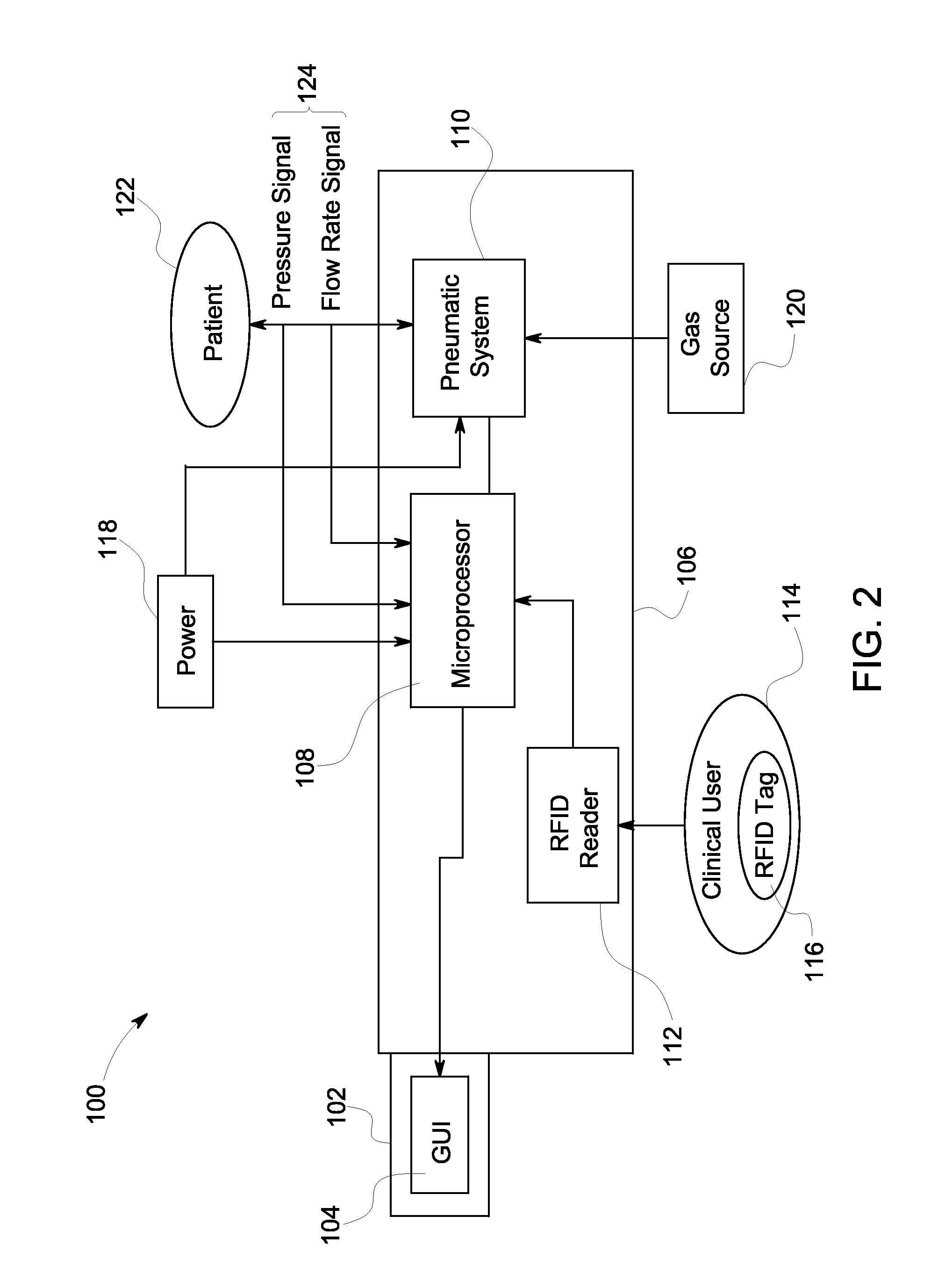
[0021]Referring to FIGS. 1 and 2, respectively a pictorial view and a block diagram of a hospital monitoring system incorporating embodiments of the invention is illustrated. And, although the system illustrated is referred to as a ventilator, it is contemplated that the system illustrated may be an anesthesia machine or a vital signs monitoring machine incorporating embodiments of the invention. Ventilator 100 includes a display 102 that includes a screen 104. Screen 104 includes a touch-sensitive screen, or touchscreen, that may be used to input paramet...


PUM


Abstract

A device for monitoring physiological parameters of a medical patient includes a pneumatic system configured to be coupled to a patient to provide a regulated gas thereto, a computer coupled to the pneumatic system and configured to regulate gas to the patient via the pneumatic system, and a touchscreen monitor coupled to the computer. The touchscreen monitor includes a first graphical user interface (GUI) having a first display, and a second GUI having a second display different from the first display and configured having interaction fields to enable parameters to be input therewith. The device includes a first trigger configured to switch at least from the first GUI to the second GUI.

Description

BACKGROUND OF THE INVENTION[0001]Embodiments of the invention relate generally to equipment for monitoring physiological parameters of a medical patient and, more particularly, to an apparatus and method of accessing and controlling a user interface for monitoring and treatment equipment in a medical environment.[0002]Equipment for monitoring physiological parameters of a medical patient and patient treatment include ventilators, anesthesia machines, and vital signs monitoring equipment that are often located in a hospital or medical environment. The environment may include an intensive care unit (ICU) or a pediatric ward, as examples. A patient is monitored in the environment for extended periods of time while medical personnel pass in and out of the environment during a normal course of business.[0003]Patients that have respiratory difficulties often are placed on a ventilator. These respiratory difficulties may be pathological in nature or may be due to the fact that the patient ...

Claims


Application Information

Patent Timeline
Patent Type & Authority Applications(United States)
IPC IPC(8): A61B5/00G06F3/041H04Q5/22G06F3/00G06F3/048
CPCH04Q2213/13095A61B5/08A61B5/7435
Inventor GEORGIEV, EMIL MARKOVMCCORMICK, TIMOTHY PATRICKWENZL, JOEL PATRICKDOMANICO, MAUREEN MARIEREDAELLI, FABRIZIOKORTEN, JEROME BODA
Owner GENERAL ELECTRIC CO
Why Eureka
Try Eureka