Optical position detecting device and apparatus provided with position detecting function

Inactive Publication Date: 2012-05-24
COLUMBIA PEAK VENTURES LLC
View PDF3 Cites 5 Cited by
  • Summary
  • Abstract
  • Description
  • Claims
  • Application Information

AI Technical Summary

Benefits of technology

[0011]In the above-described optical position detecting device, the plurality of light emitting devices are mounted on the band-shaped flexible substrate, and the plurality of light emitting devices emit detection light. Accordingly, the position of a target object in the emission space can be detected based on the result of reception of the detection light, which is reflected by a target object located in the emission space of the detection light, in the light receiving unit. Here, since the flexible substrate is arranged so as to overlap the convex face of the substrate supporting member, the flexible substrate is bent in a predetermined shape along the convex face. Accordingly, the detection light can be emitted over a wide angle range from the position in which the flexible substrate is arranged, and therefore, the position of the target object can be detected in a broad area. In addition, since the flexible substrate is bent along the convex face of the substrate supporting member, the great effort for precisely bending the flexible substrate is not necessary, and the flexible substrate can be maintained in a bent shape in an easy manner. Furthermore, in the substrate supporting member, a notch is formed at a position overlapping the end portion of the flexible substrate. Accordingly, when one end portion of the flexible substrate is positioned, the other end portion can be inserted into the notch. Therefore, even in a case where the size of the flexible substrate is too large, the flexible substrates can be arranged so as to overlap the convex face of the substrate supporting member, and whereby there is no floating of the flexible substrates. Accordingly, the plurality of light emitting devices can be precisely arranged so as to face in a predetermined direction. As a result, the plurality of light emitting devices can emit the detection light in a predetermined direction, whereby the position of the target object can be detected with high precision.
[0012]The above-described optical position detecting device may be configured such that an emission intensity monotonously changes from one end of the convex face in the longitudinal direction toward the other end side when the detection light is emitted from the light source units. In such a configuration, a light intensity distribution can be formed in the emission space of the detection light, and accordingly, the position of the target object can be detected by using the intensity distribution. Even in such a configuration, since the plurality of light emitting devices are arranged so as to precisely face in a predetermined direction, a predetermined light intensity distribution can be formed in the emission space of the detection light. Therefore, the position of the target object can be detected with high precision.
[0013]The above-described optical position detecting device may be configured such that a band-shaped first flexible substrate and a band-shaped second flexible substrate that is arranged in parallel with the first flexible substrate in a width direction of the first flexible substrate are included as the flexible substrate, the plurality of light emitting devices mounted on the first flexible substrate and the plurality of light emitting devices mounted on the second flexible substrate are turned on at different timings, the emission intensity increases from the one end of the convex face in the longitudinal direction toward the other end side in the plurality of light emitting devices mounted on the first flexible substrate, and the emission intensity decreases from the one end of the convex face in the longitudinal direction toward the other end side in the plurality of light emitting devices mounted on the second flexible substrate. In such a configuration, a first light intensity distribution formed by the plurality of light emitting devices mounted on the first flexible substrate and a second light intensity distribution formed by the plurality of light emitting devices mounted on the second flexible substrate are formed such that the intensities of the detection light thereof change in opposite directions. Accordingly, the position of the target object can be detected based on the result of reception of light in the light receiving unit at the time of forming the first light intensity distribution and the result of reception of light in the light receiving unit at the time of forming the second light intensity distribution. Even in such a configuration, the plurality of light emitting devices are arranged so as to precisely face in a predetermined direction, and accordingly a predetermined light intensity distribution can be formed in the emission space of the detection light. Therefore, the position of the target object can be detected with high precision.

Problems solved by technology

Accordingly, there are many problems to be solved for detecting the position of a target object in a broad area such as a screen face of a projection-type display apparatus, a screen face of an electronic blackboard, digital signage, or the like.
However, according to such a method, it takes extensive labor to accurately bend the band-shaped flexible substrate so as to allow the light emitting devices to be positioned in a predetermined direction, and it is difficult to fix the flexible substrate in such a state.
However, in a case where the position of the flexible substrate is deviated due to a deviation in the size of the flexible substrate, there is a problem in that it is difficult to detect the position of the target object with high precision due to the deviation in the position of the light emitting devices.

Method used


Image

  • Optical position detecting device and apparatus provided with position detecting function
  • Optical position detecting device and apparatus provided with position detecting function
  • Optical position detecting device and apparatus provided with position detecting function

Examples


embodiment 1

Entire Configuration

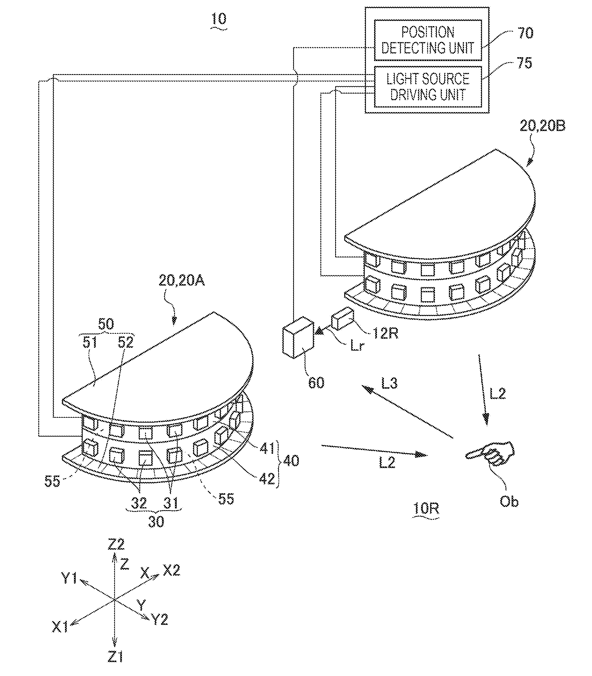
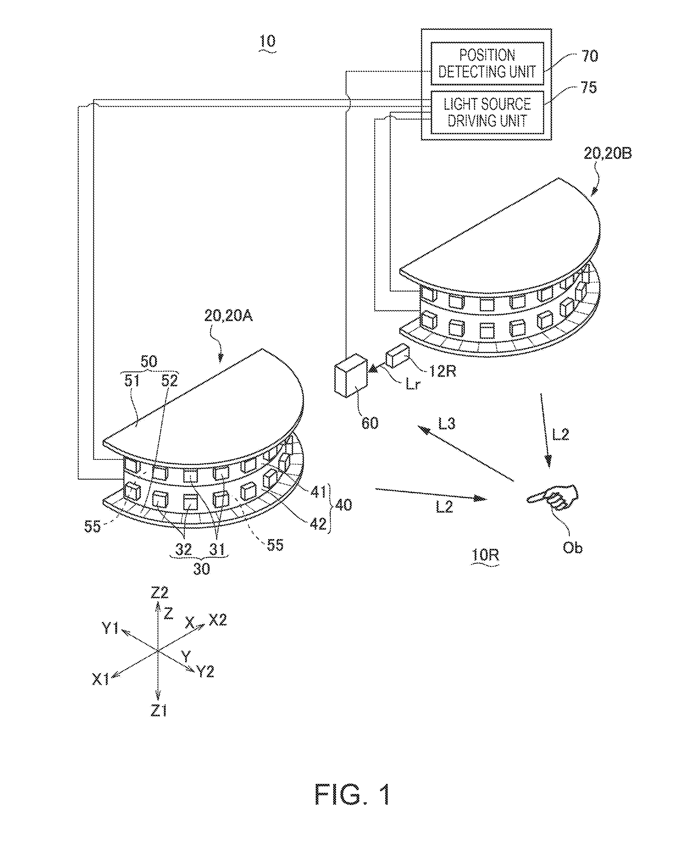
[0035]FIG. 1 is an explanatory diagram schematically illustrating the entire configuration of an optical position detecting device according to Embodiment 1 of the invention.

[0036]In FIG. 1, the optical position detecting device 10 according to this embodiment is a device that detects the position (X coordinate) of a target object Ob located in a detection target space 10R in the X direction and the position (Y coordinate) of the target object Ob in the Y direction. The optical position detecting device 10 includes a light source unit 20 that emits detection light L2 and a light receiving unit 60 that receives detection light L3 reflected by the target object Ob located in the emission space (a detection target space 10R) of the detection light L2. In addition, the optical position detecting device 10 includes a light source driving unit 75 that is used for driving the light source unit 20 and a position detecting unit 70 that detects the position (the X coordina...

embodiment 2

[0062]FIGS. 7A and 7B are explanatory diagrams of a light source unit 20 of an optical position detecting device 10 according to Embodiment 2 of the invention. FIGS. 7A and 7B are a perspective view and an exploded perspective view of the light source unit 20. FIG. 8 is an exploded perspective view acquired by disassembling the light source unit 20 of the optical position detecting device 10 according to Embodiment 2 of the invention into pieces. FIGS. 9A to 9C are explanatory diagrams illustrating the appearance of attaching a second flexible substrate 42 to a second substrate supporting member 52 in the optical position detecting device 10 according to Embodiment 2 of the invention. FIGS. 9A, 9B, and 9C are explanatory diagrams illustrating the second flexible substrate 42 positioned in various states. Since the basic configuration of this embodiment is similar to that of Embodiment 1, the same reference signal is assigned to a common portion, and the description thereof is not pr...

embodiment 3

[0069]FIGS. 10A and 10B are explanatory diagrams of a light source unit 20 of an optical position detecting device 10 according to Embodiment 3 of the invention. FIGS. 10A and 10B are a perspective view and an exploded perspective view of the light source unit 20. FIGS. 11A and 11B are explanatory diagrams showing the detailed configuration of the light source unit 20 of the optical position detecting device 10 according to Embodiment 3 of the invention. FIGS. 11A and 11B are an exploded perspective view of the light source unit 20 that is further exploded and a cross-sectional view of a main portion thereof. Since the basic configuration of this embodiment is similar to that of Embodiment 1, the same reference signal is assigned to a common portion, and the description thereof is not presented here.

[0070]As shown in FIGS. 10A, 10B, and 11, the light source unit 20 used in the optical position detecting device 10 according to this embodiment, similarly to those of Embodiments 1 and ...


PUM


Abstract

In a light source unit of an optical position detecting device, a plurality of light emitting devices are mounted on a band-shaped flexible substrate, and the plurality of light emitting devices emit detection light. The flexible substrate is arranged so as to overlap a convex face of a substrate supporting member, and accordingly, in a case where the flexible substrate is too long, the end portion of the flexible substrate can be inserted into a notch. Therefore, there is no case in which the flexile substrate floats.

Description

BACKGROUND[0001]1. Technical Field[0002]The present invention relates to an optical position detecting device that optically detects the position of a target object and an apparatus provided with a position detecting function that includes the optical position detecting device.[0003]2. Related Art[0004]As an optical position detecting device that optically detects a target object, for example, a device is proposed in which detection light is emitted from a plurality of detection light sources toward the target object through a light transmitting member, and the detection light reflected by the target object is transmitted through the light transmitting member so as to be detected by a light receiving unit. In the optical position detecting device having such a configuration, the position of the target object is detected based on a detection result of the detection light in the light receiving unit (for example, see JP-T-2003-534554).[0005]In addition, a method is also proposed in wh...

Claims


Application Information

Patent Timeline
IPC IPC(8): G01B11/14
CPCG01C3/08G01S3/784G06F3/0428G01S7/4815G06F3/017G01S5/16
Inventor KIYOSE, KANECHIKA
Owner COLUMBIA PEAK VENTURES LLC
Why Eureka
Try Eureka