Fan

Inactive Publication Date: 2009-03-05
DYSON TECH LTD
View PDF103 Cites 167 Cited by
  • Summary
  • Abstract
  • Description
  • Claims
  • Application Information

AI Technical Summary

Benefits of technology

[0024]Preferably the nozzle comprises a loop. The shape of the nozzle is not constrained by the requirement to include space for a bladed fan. In a preferred embodiment the nozzle is annular. By providing an annular nozzle the fan can potentially reach a broad area. In a further preferred embodiment the nozzle is at least partially circular. This arrangement can provide a variety of design options for the fan, increasing the choice available to a user or customer.
[0025]Preferably, the interior passage is continuous, more preferably substantially annular. This allows smooth, unimpeded air flow within the nozzle and reduces frictional losses and noise. In this arrangement the nozzle can be manufactured as a single piece, reducing the complexity of the fan assembly and thereby reducing manufacturing costs.
[0026]In the preferred fan arrangement the means for creating an air flow through the nozzle is arranged to create an air flow through the nozzle having a pressure of at least 400 kPa. This pressure is sufficient to overcome the pressure created by the constriction caused by the mouth of the nozzle and provides pressure for an output air flow suitable for cooling a user. More preferably, in use, the mass flow rate of air projected from the fan assembly is at least 450 l/s, most preferably in the range from 600 l/s to 700 l/s. Advantageously this mass flow rate can be projected forward from the opening and the area surrounding the mouth of the nozzle with a laminar flow and ca

Problems solved by technology

A disadvantage of this type of arrangement is that the forward flow of air current produced by the rotating blades of the fan is not felt uniformly by the user.
Uneven or ‘choppy’ air flow can be felt as a series of pulses or blasts of air and can be noisy.
A further disadvantage is that the cooling effect created by the fan diminishes with distance from the user.
It is undesirable for parts to project from the appliance, or for the user to be able to touch any moving parts of the fan, such as the blades.
U.S. D 103,476 shows a type of cage around the blades however, caged

Method used


Image

  • Fan
  • Fan
  • Fan

Examples


Example

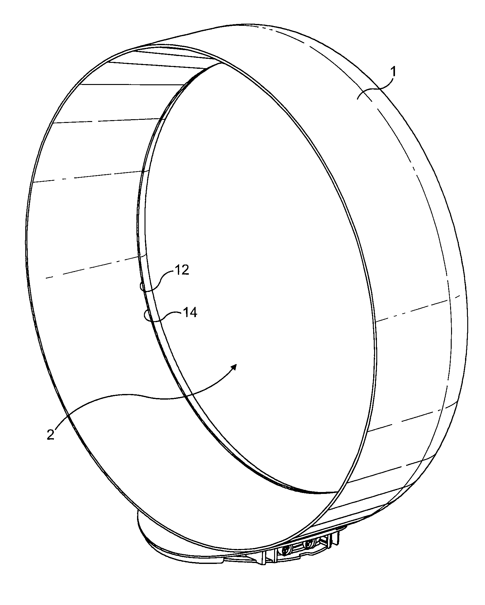
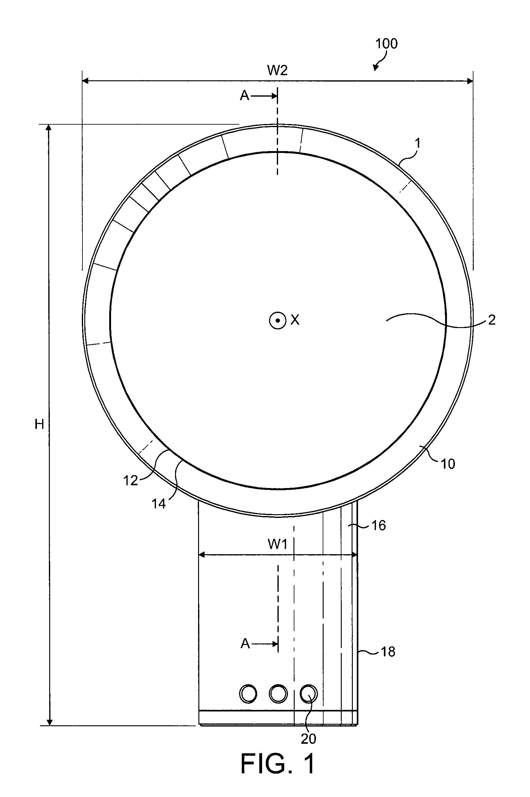
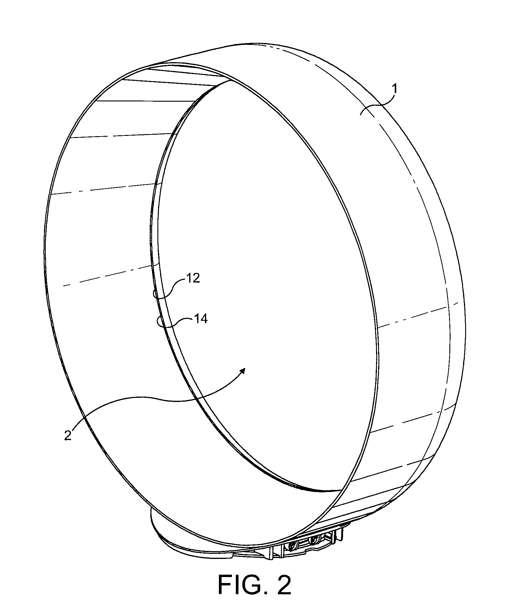
[0036]FIG. 1 shows an example of a fan assembly 100 viewed from the front of the device. The fan assembly 100 comprises an annular nozzle 1 defining a central opening 2. With reference also to FIGS. 2 and 3, nozzle 1 comprises an interior passage 10, a mouth 12 and a Coanda surface 14 adjacent the mouth 12. The Coanda surface 14 is arranged so that a primary air flow exiting the mouth 12 and directed over the Coanda surface 14 is amplified by the Coanda effect. The nozzle 1 is connected to, and supported by, a base 16 having an outer casing 18. The base 16 includes a plurality of selection buttons 20 accessible through the outer casing 18 and through which the fan assembly 100 can be operated. The fan assembly has a height, H, width, W, and depth, D, shown on FIGS. 1 and 3. The nozzle 1 is arranged to extend substantially orthogonally about the axis X. The height of the fan assembly, H, is perpendicular to the axis X and extends from the end of the base 16 remote from the nozzle 1 t...


PUM


Abstract

A bladeless fan assembly includes comprising a nozzle mounted on a base housing a device creating an air flow through the nozzle. The nozzle includes an interior passage receiving the air flow from the base and a mouth through which the air flow is emitted. The nozzle extends substantially orthogonally about an axis to define an opening through which air from outside the fan assembly is drawn by the air flow emitted from the mouth. The depth of the base in the direction of the axis may be no more than twice the depth of the nozzle. The assembly produces an air current without requiring a bladed fan, that is, the air flow is created by a bladeless fan.

Description

REFERENCE TO RELATED APPLICATIONS[0001]This application claims the priority of United Kingdom Application Nos. 0717155.6, 0717148.1, 0717151.5 and 0717154.9, all filed Sep. 4, 2007, and No. 0814866.0, filed Aug. 14, 2008, the contents of which prior applications are incorporated herein by reference.FIELD OF THE INVENTION[0002]The present invention relates to a fan appliance. Particularly, but not exclusively, the present invention relates to a domestic fan, such as a desk fan, for creating air circulation and air current in a room, in an office or other domestic environment.BACKGROUND OF THE INVENTION[0003]A number of types of domestic fan are known. It is common for a conventional fan to include a single set of blades or vanes mounted for rotation about an axis, and driving apparatus mounted about the axis for rotating the set of blades. Domestic fans are available in a variety of sizes and diameters, for example, a ceiling fan can be at least 1 m in diameter and is usually mounted...

Claims


Application Information

Patent Timeline
IPC IPC(8): F01D1/36
CPCF04D25/06F04D25/08F04F5/46F04F5/16F04D29/681F04D29/44F04D29/40F04D33/00
Inventor GAMMACK, PETER DAVIDNICOLAS, FREDERICSIMMONDS, KEVIN JOHN
Owner DYSON TECH LTD
Why Eureka
Try Eureka