Device for welding

Inactive Publication Date: 2005-04-05
SMK CO LTD
View PDF14 Cites 14 Cited by
  • Summary
  • Abstract
  • Description
  • Claims
  • Application Information

AI Technical Summary

Benefits of technology

With the pin coupling of the variable coupling structure being disposed on the upper end of the coupling rod, a positioning pin that is made of ceramics which are highly durable, but make it impossible for the positioning pin to be threaded,

Problems solved by technology

In the case where the projected position of a positioning pin that can be moved into and out of the lower electrode is detected to detect a nut setting failure or the like, the device tends to be large in size due to the mounted detector, and if the actuating rod or the coupling rod which is coupled to the positioning pin is tilted when lifted or lowered, the positional accuracy is liable to suffer an error, making it difficult to detect a failure with accuracy.
For example, a welding failure of

Method used


Image

  • Device for welding
  • Device for welding
  • Device for welding

Examples


Example

The present invention will hereinafter be described in detail below with reference to the drawings.

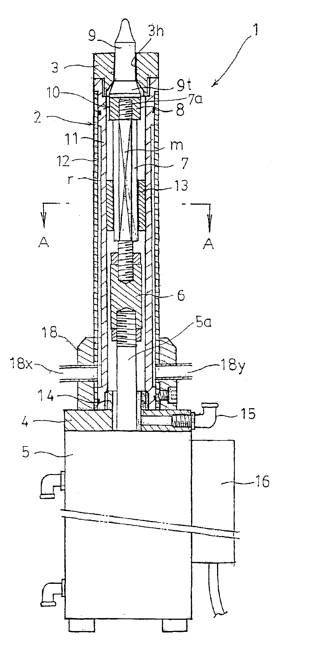
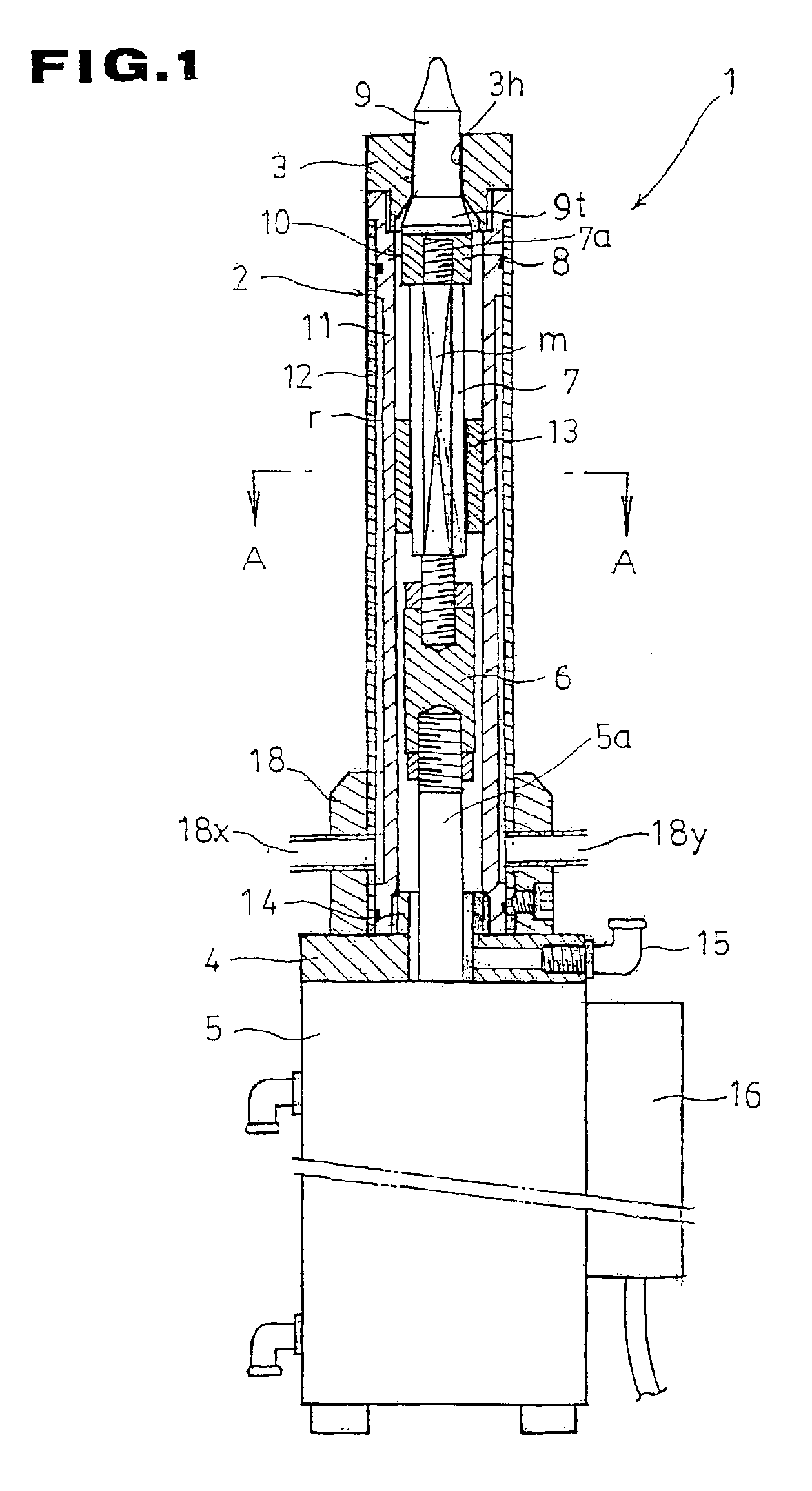
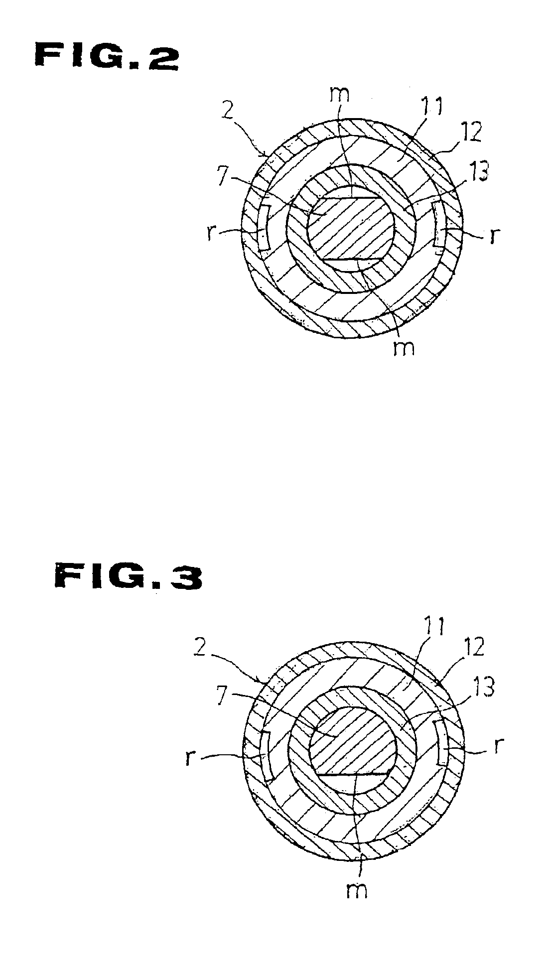
An device 1 for welding a nut or the like according to the present invention is capable of detecting the projected position of a positioning pin with accuracy and of preventing sputtering particles produced upon welding from entering a tube of a holder for increased durability. As shown in FIG. 1, the device 1 has a double-tube electrode holder 2, a lower electrode 3 coupled to an upper portion of the electrode holder 2, and an air cylinder 5 coupled to a lower portion of the electrode holder 2 with an insulating member 4 interposed therebetween. The air cylinder 5 has a cylinder rod 5a coupled to a coupling rod 7 by an insulating member 6. A pin coupling 10 is mounted on an upper portion of the coupling rod 7, and a positioning pin 9 made of ceramics is mounted on the pin coupling 10 by a nut seat 8.

The lower electrode 3 has a through hole 3h defined centrally therein and having in a ...


PUM

PropertyMeasurementUnit
Lengthaaaaaaaaaa
Magnetic fieldaaaaaaaaaa
Magnetismaaaaaaaaaa

Abstract

The present invention relates to a nut positioning pin disposed on a lower electrode for the projection welding of a nut. The present invention increases cooling and positioning accuracy, prevents entrance of sputtering particles, and increases the detecting accuracy. The present invention comprises an electrode holder (2) of a double-tube structure having a cooling water passage, a guide ring (13) for guiding a coupling rod (7) for vertical movement, an air passage (m) for preventing the entrance of sputtering particles, a coupling block (28) and a magnetic shield, which comprises a magnetic member for preventing a magnetic detecting element from being affected by an external magnetic field. The present invention accurately guides cooling water and the coupling rod in the electrode holder and prevents sputtering particles from entering the electrode holder, and prevents a detector from being adversely influenced by an external magnetic field for increased detecting accuracy.

Description

TECHNICAL FIELDThe present invention relates to a technology for preventing a welding failure or the like in the projection welding of nuts and bolts.BACKGROUND ARTHeretofore, there is known a technology for projection-welding nuts and bolts to a steel sheet which has guide holes for the insertion of bolt shanks by setting the steel sheet on a lower electrode, lifting a positioning pin through a through hole in the lower electrode so as to project upwardly through a guide hole in the steel sheet, positioning a nut to be set on an upper surface of the steel sheet, thereafter lowering an upper electrode to press the nut against the steel sheet, and passing a current through the upper electrode and the lower electrode to weld the nut to the steel sheet. There are known techniques as disclosed in Japanese laid-open patent publications Nos. 7-9165 and 7-100660 for preventing a failure such as a reversed nut orientation or an improper nut attachment.According to former Japanese laid-open ...

Claims


Application Information

Patent Timeline
IPC IPC(8): B23K11/30B23K11/14
CPCB23K11/14B23K11/3081B23K11/3018
Inventor HIDAKA, MASATO
Owner SMK CO LTD
Why Eureka
Try Eureka