Integrated variable geometry flow restrictor and heat exchanger

a heat exchanger and variable geometry technology, applied in the direction of machines/engines, liquid fuel engines, light and heating apparatus, etc., can solve the problems of affecting the engine performance benefit, the heat exchanger in the bypass duct and the bypass valve often conflict with one another, etc., to achieve low or reduced performance conflicts

Active Publication Date: 2012-05-24
GENERAL ELECTRIC CO
View PDF5 Cites 55 Cited by
  • Summary
  • Abstract
  • Description
  • Claims
  • Application Information

AI Technical Summary

Benefits of technology

[0014]Accordingly, it is desired to provide a gas turbine engine having a heat exchanger cooled by fan bypass flow and a bypass valve for regulat...

Problems solved by technology

Heat exchangers in the bypass duct and bypass valves often conflict with one another, especially if they use the same air.
Hea...

Method used


Image

  • Integrated variable geometry flow restrictor and heat exchanger
  • Integrated variable geometry flow restrictor and heat exchanger
  • Integrated variable geometry flow restrictor and heat exchanger

Examples


Embodiment Construction

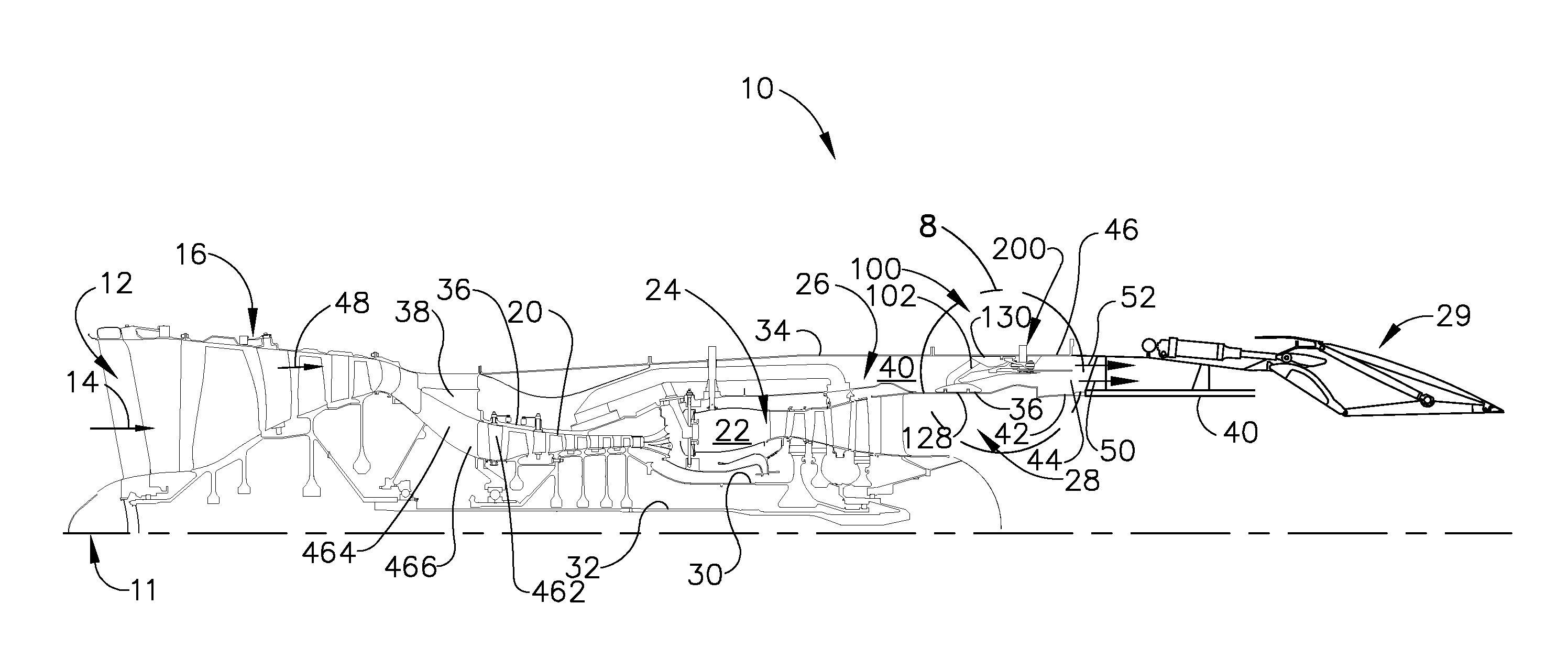
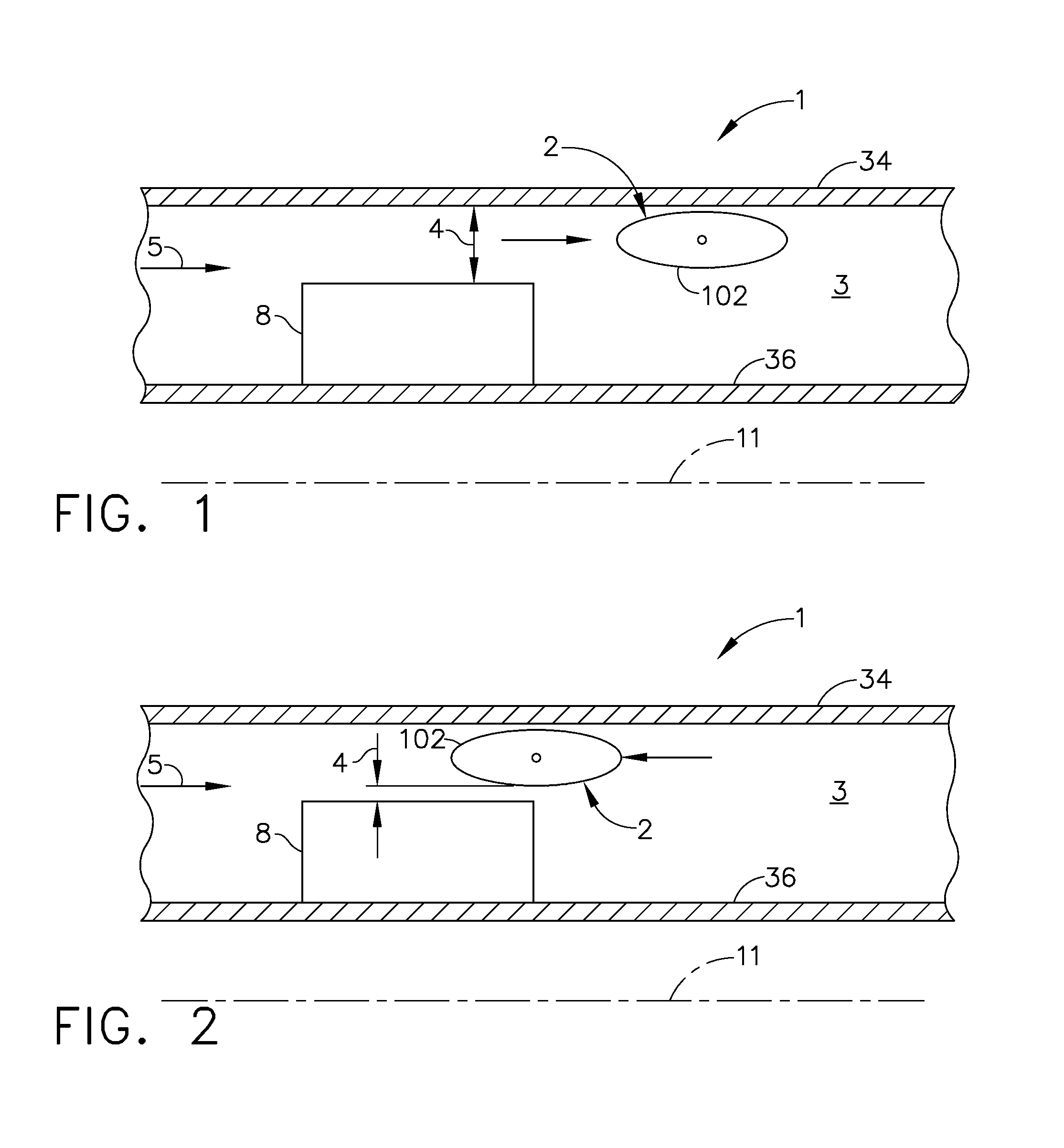
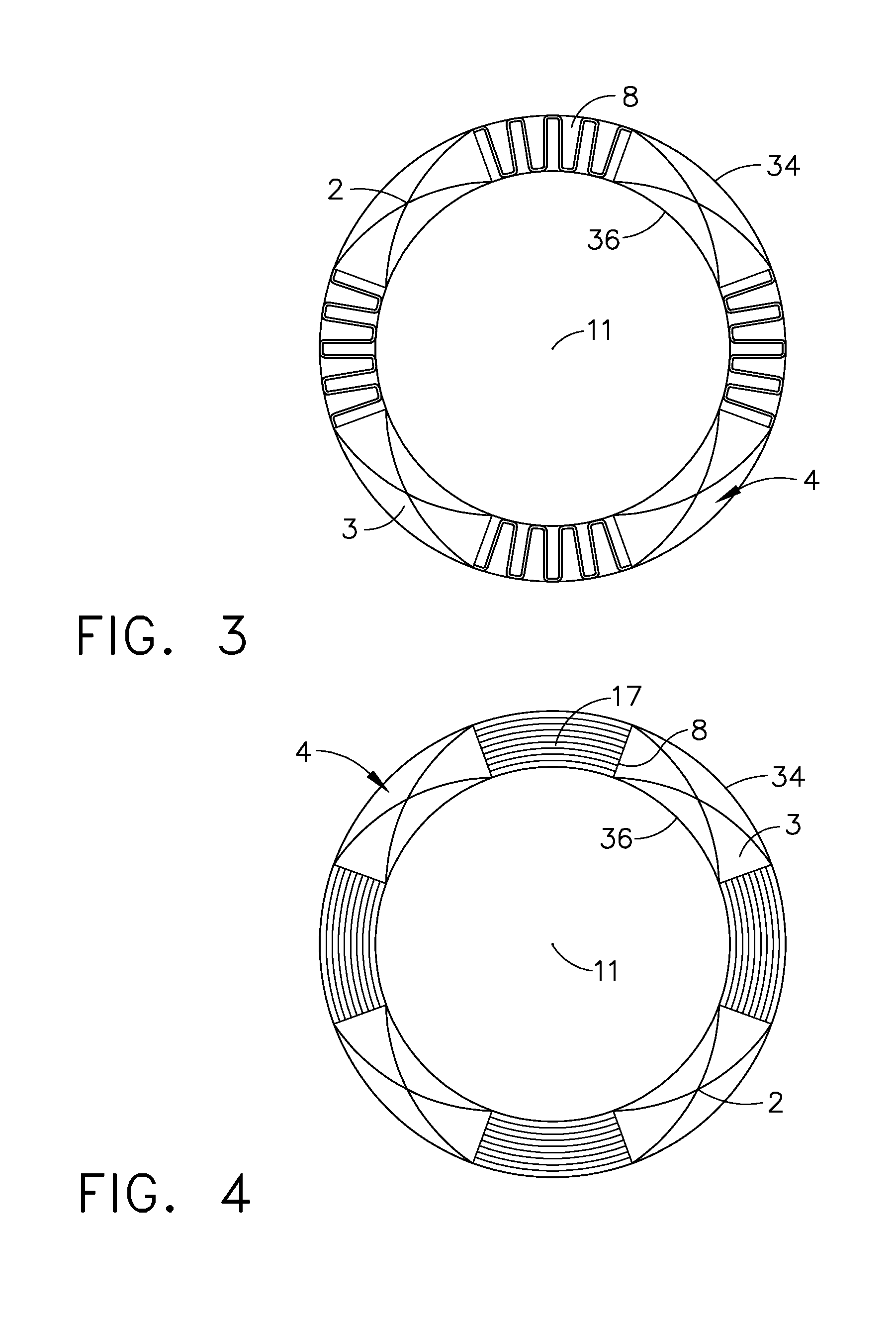
[0043]An integrated variable geometry flow restrictor and heat exchanger system 1 in a gas turbine engine annular fan bypass duct 3 circumscribed about a longitudinal centerline 11 is illustrated in FIGS. 1 and 2. An outer casing 34 radially spaced apart from an inner casing 36 bounds the fan bypass duct 3. The integrated variable geometry flow restrictor and heat exchanger system 1 illustrated in FIGS. 1 and 2 includes a heat exchanger 8 integral and in parallel flow relationship with a variable geometry flow restrictor 2.

[0044]The heat exchanger 8 is illustrated herein as being mounted on the inner casing 36 but alternatively may be mounted on the outer casing 34 or radially between the casings. The variable geometry flow restrictor 2 is illustrated in an open position in FIG. 1 and in a closed position in FIG. 2. The flow restrictor 2 is illustrated as including an annular slide valve 102 axially translatable with respect to the heat exchanger 8 and operable to open and close or ...


PUM


Abstract

One or more heat exchangers mounted in a duct have heat transfer cooling passages therein and a variable geometry flow restrictor is integral with each of the heat exchangers. An annular slide valve axially translatable within the duct is operable to open and close or vary a variable area between the heat exchangers and one of inner and outer casings bounding the duct. The heat exchangers may be being circumferentially distributed around an annular duct and include radial or circumferentially curved heat transfer tubes or vanes.

Description

BACKGROUND OF THE INVENTION[0001]1. Technical Field[0002]The present invention relates generally to heat exchangers in turbofan gas turbine engines and, more specifically, to heat exchangers and regulating flow in fan bypass ducts of the engines.[0003]2. Background Information[0004]At least some known aircraft gas turbine engines include a fan, a compressor, a combustor, a high pressure turbine, a low pressure turbine, and an augmentor or “afterburner” and an exhaust nozzle. The compressor, combustor, high pressure turbine, and low pressure turbine are collectively referred to as a core engine or engine core.[0005]Airflow entering the fan is compressed. Airflow exiting the fan is split such that a portion of the flow referred to as core engine flow is directed into the compressor and the remaining portion of the airflow, referred to as fan bypass flow, is directed into a bypass duct or passage where it bypasses the compressor, the combustor, the high pressure turbine, and the low pr...

Claims


Application Information

Patent Timeline
IPC IPC(8): F01D25/12F28F1/10F01D5/18F28F27/02
CPCF01D5/146Y02T50/676F02C3/13F02C7/08F02C7/14F02C7/185F02K1/06F02K1/08F02K1/1207F02K3/075F05D2260/56F28D11/04F28F1/02F28F13/08Y02T50/673F01D5/18F01D17/162F01D17/165F02C7/143F02C9/18F01D25/12Y02T50/60
Inventor RUTHEMEYER, MICHAEL ANTHONY
Owner GENERAL ELECTRIC CO
Why Eureka
Try Eureka