Connector

Inactive Publication Date: 2012-05-24
CHENG UEI PRECISION IND CO LTD
View PDF5 Cites 3 Cited by
  • Summary
  • Abstract
  • Description
  • Claims
  • Application Information

AI Technical Summary

Benefits of technology

[0006]As described above, the fixing slice is received in the fixing recess for fixing the first holding slice

Problems solved by technology

However, as the first holding slice and the second holding slice are not fixed well, the soldering slice may be knocked by the bott

Method used


Image

  • Connector
  • Connector
  • Connector

Examples


Embodiment Construction

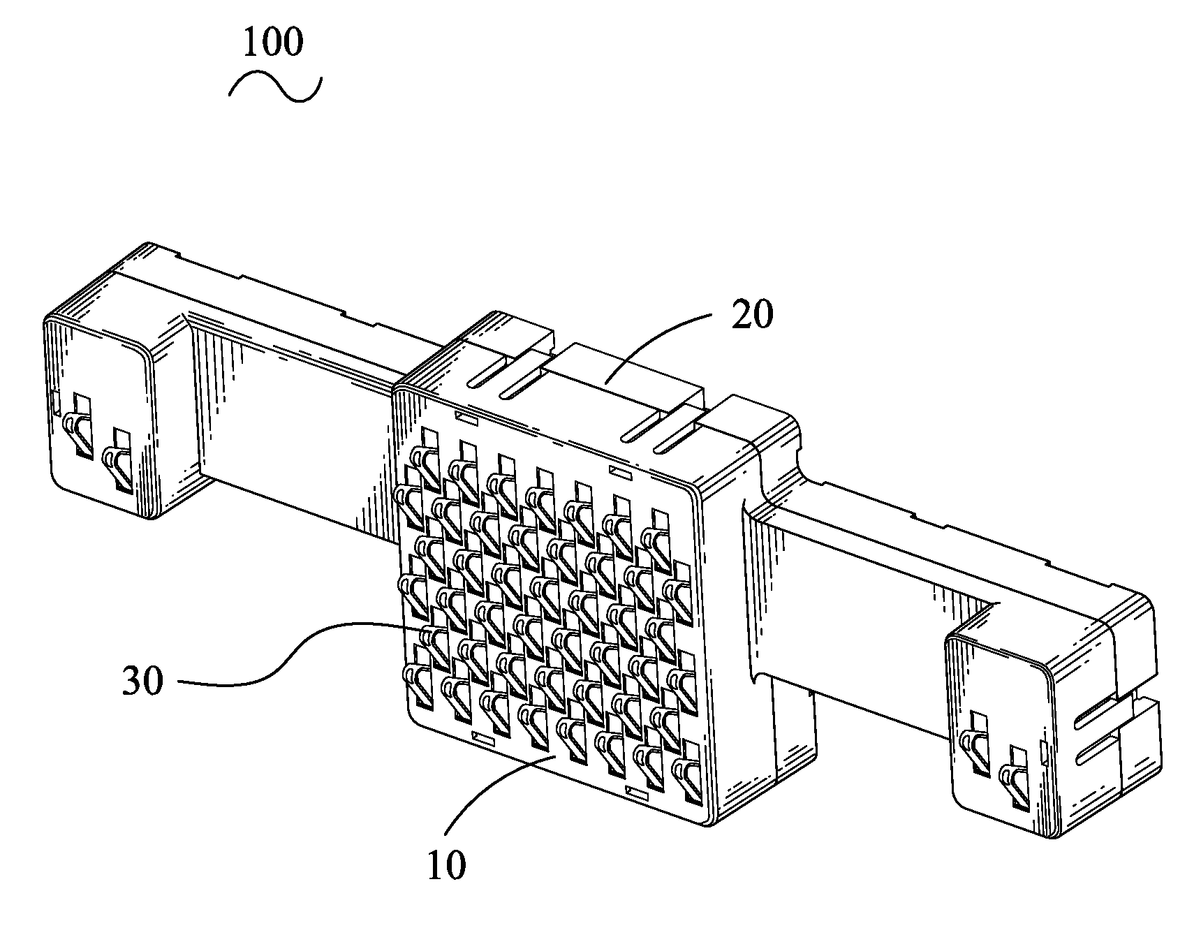
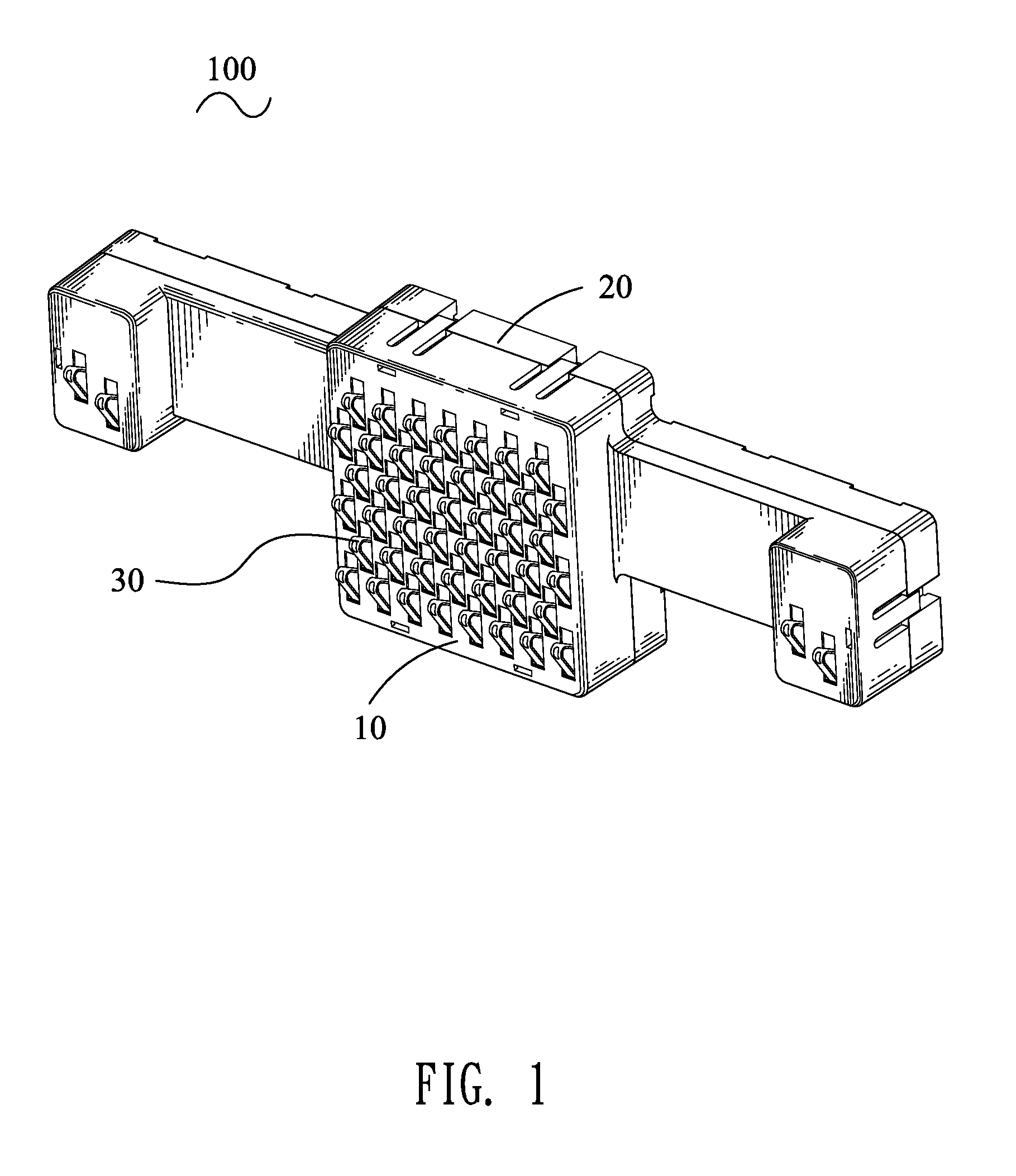
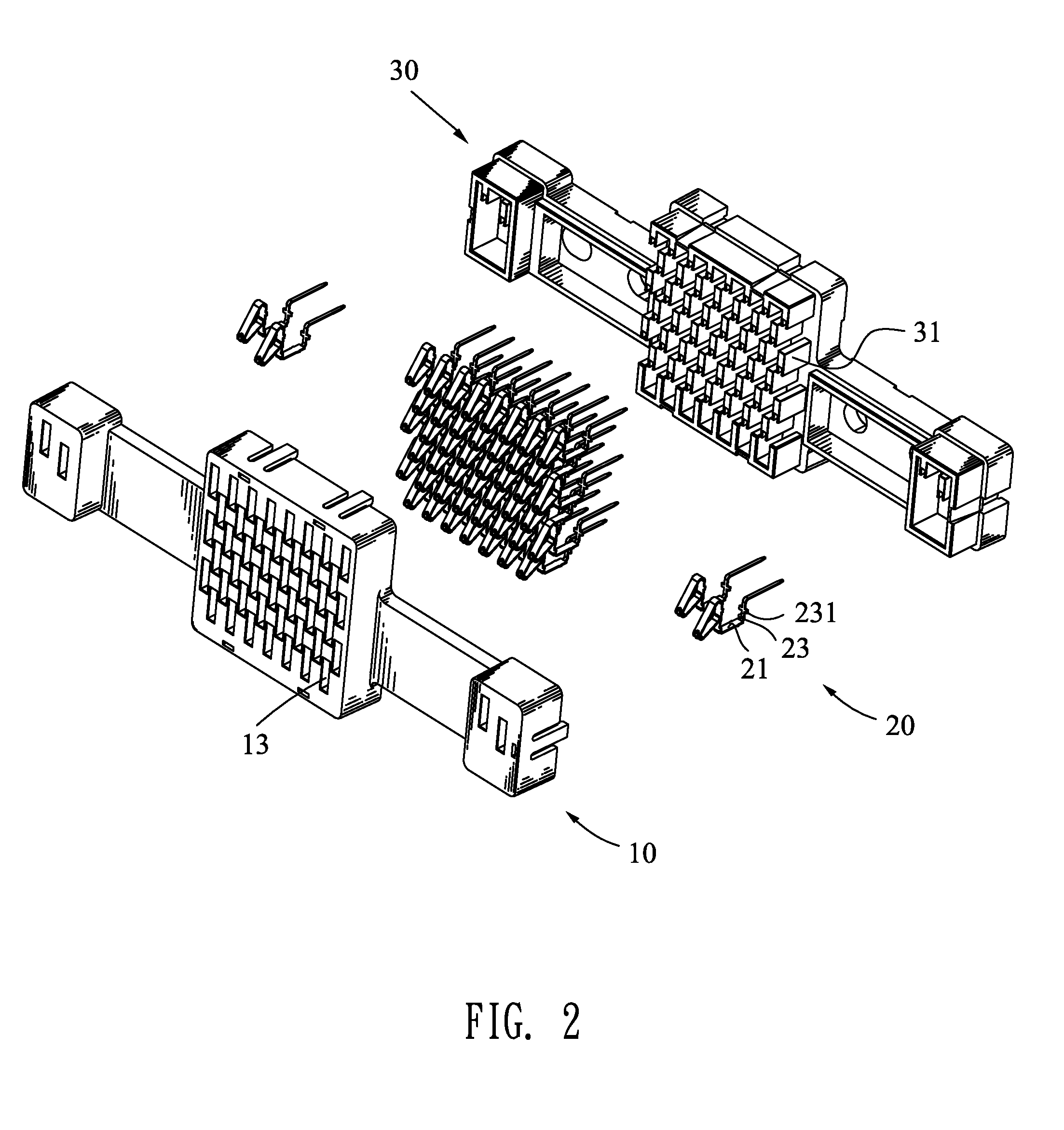
[0016]Referring to the drawings in greater detail, and first to FIGS. 1-2, the embodiment of the invention is embodied in a connector 100. The connector 100 has a top housing 10, a bottom housing 30 coupled with the top housing 10, a plurality of terminals 20 mounted in the top housing 10.

[0017]With reference to FIGS. 2-5, the terminals 20 fixed on the top housing 10 has a base slice 21 which has barbs 211 formed at a substantially middle portion thereof. A bottom and a top of the base slice 21 are extended toward the same direction to form a first holding slice 23 and a second holding slice 22, respectively. A free end of the second holding slice 22 is connected with an elastic arm 24 of substantially inverted-V shape with an opening facing to the second holding slice 22. The elastic arm 24 has an apex formed with a contacting portion 25. The second holding slice 22 has lateral sides thereof extended outward to form two pairs of buckling slices 221. The first holding slice 23 has l...


PUM


Abstract

A connector has a top housing, a bottom housing coupled with the top housing, a plurality of terminals mounted in the top housing. The terminal has a base slice. The base slice is bent perpendicularly to form a first holding slice which has lateral sides extended outward to form a pair of fixing slices. The top housing is recessed to form a plurality of receiving passages. The receiving passage has a bottom thereof recessed to form a pair of fixing recesses. The terminal is received in the receiving passage. The fixing slices are received in the fixing recesses, which prevents the soldering slice to be knocked while assembling the bottom housing to the top housing.

Description

BACKGROUND OF THE INVENTION[0001]1. Field of the Invention[0002]The present invention relates to an electrical connector, and more particularly to a connector that is convenient to assembly.[0003]2. The Related Art[0004]A conventional connector has a top housing, a bottom housing coupled with the top housing, a plurality of terminals mounted into the top housing. The top housing has a plurality of receiving passages therethrough. The terminals mounted into the receiving passages has a base slice, a first holding slice and a second holding slice respectively extended from two opposite ends of the base slice. A free end of the second holding slice is extended downward to form a soldering slice. However, as the first holding slice and the second holding slice are not fixed well, the soldering slice may be knocked by the bottom housing to be out of shape, which affects the quality of the product and brings difficulty to the assembly of the bottom housing.SUMMARY OF THE INVENTION[0005]Ac...

Claims


Application Information

Patent Timeline
IPC IPC(8): H01R13/514
CPCH01R12/58H01R13/2442H01R12/716
Inventor HSU, YA-HUIYANG, MEI-CHUAN
Owner CHENG UEI PRECISION IND CO LTD
Why Eureka
Try Eureka