Structure installation rack, method for installing the same, structure connecting structure, connection member and method for installing this structure connecting structure, and solar cell system

Active Publication Date: 2012-05-31
SHARP KK
View PDF9 Cites 34 Cited by
  • Summary
  • Abstract
  • Description
  • Claims
  • Application Information

AI Technical Summary

Benefits of technology

[0069]Because the present invention is constituted as above, even if there are numerous solar cell modules, they can be securely supported, only a few parts are needed, and the ins

Problems solved by technology

Since a solar cell module in the form of a flat panel is susceptible to high

Method used


Image

  • Structure installation rack, method for installing the same, structure connecting structure, connection member and method for installing this structure connecting structure, and solar cell system
  • Structure installation rack, method for installing the same, structure connecting structure, connection member and method for installing this structure connecting structure, and solar cell system
  • Structure installation rack, method for installing the same, structure connecting structure, connection member and method for installing this structure connecting structure, and solar cell system

Examples


Example

[0122]Embodiments of the structure installation rack, a method for installing this structure installation rack, a structure connecting structure, connecting members and an installation method for this structure connecting structure, and a solar cell system according to the present invention will now be described in detail through reference to the appended drawings.

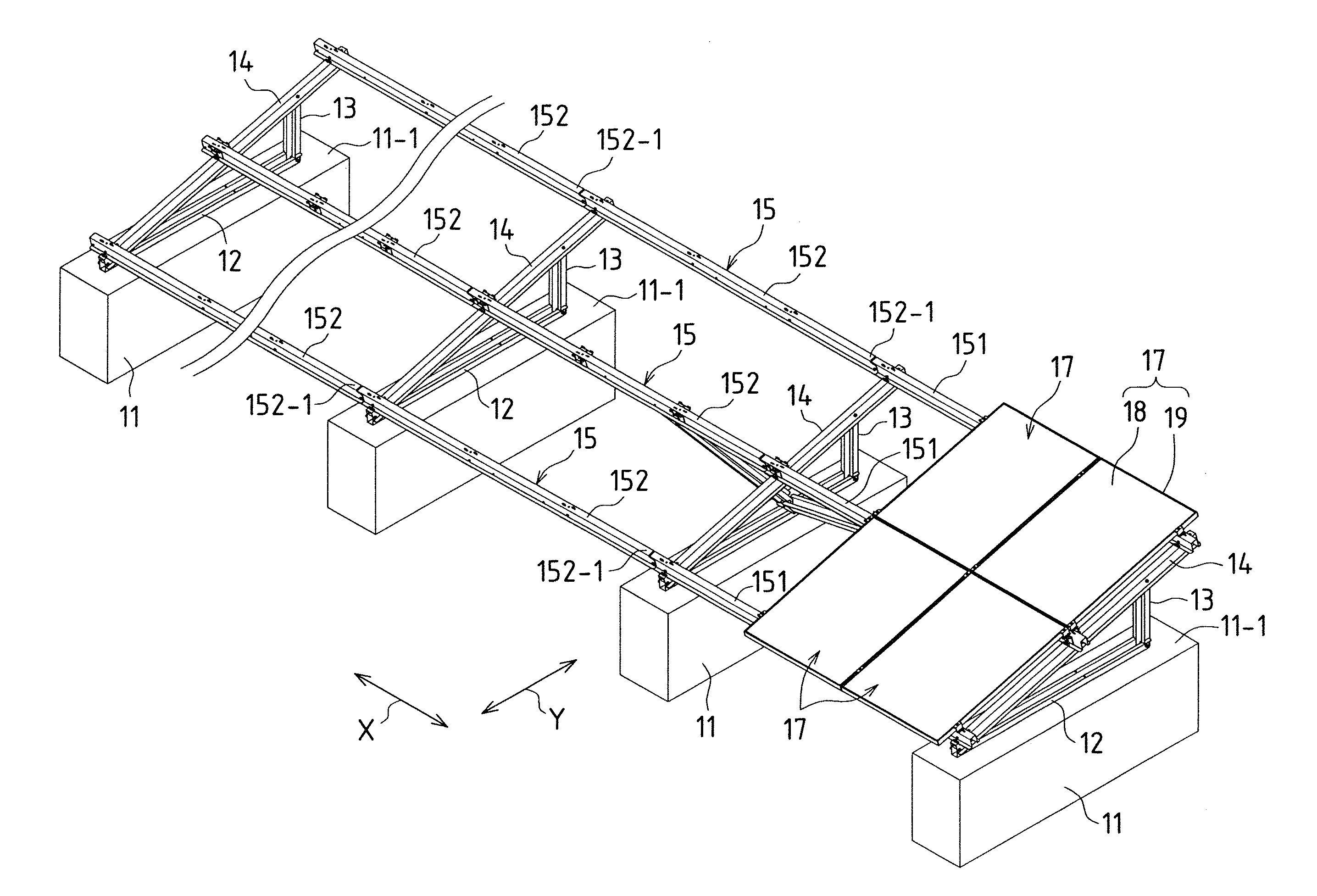
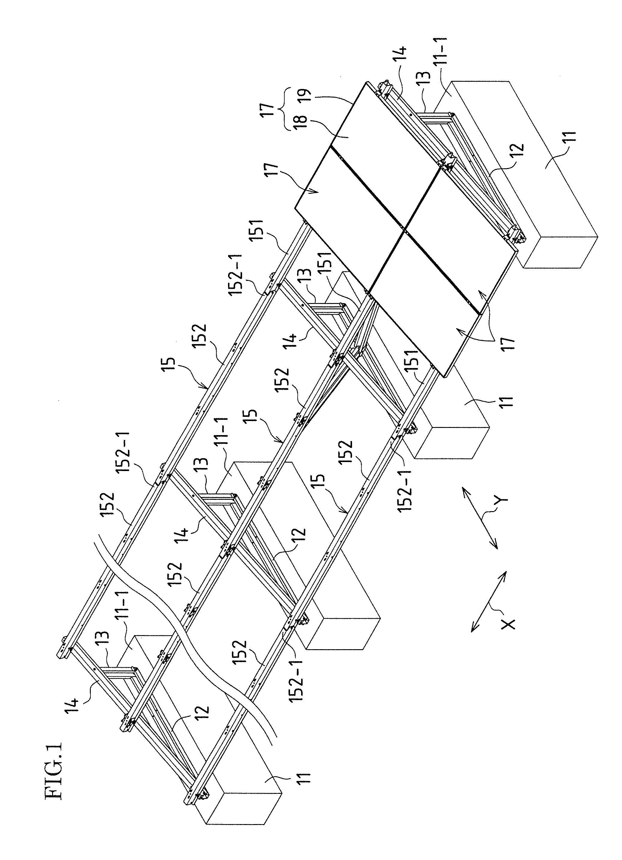
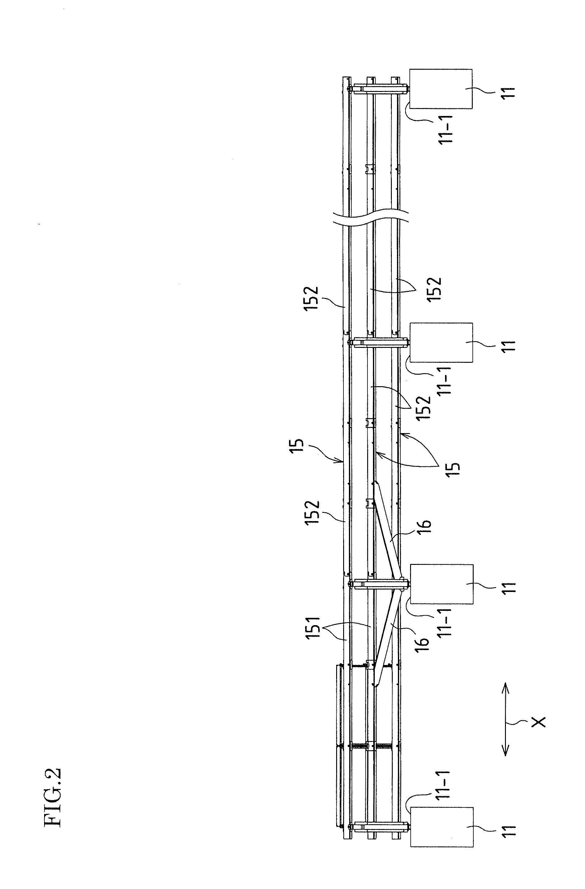
[0123]FIG. 1 is a perspective view of a solar cell system to which an embodiment of the present invention has been applied. FIG. 2 is a rear view of the solar cell system in FIG. 1, and FIG. 3 is a partially enlarged perspective view of the solar cell system in FIG. 1.

[0124]This solar cell system is premised on use in a large-scale power generating plant, and the structure installation rack of this embodiment is used to install numerous solar cell modules.

[0125]As shown in FIGS. 1, 2, and 3, with the structure installation rack of this embodiment, a plurality of concrete foundations 11 are placed equidistantly on the groun...


PUM

PropertyMeasurementUnit
Lengthaaaaaaaaaa
Shapeaaaaaaaaaa
Distanceaaaaaaaaaa

Abstract

A structure installation rack in one embodiment is formed with horizontal rails (15) obtained by connecting a plurality of rail members (151, 152) having a pair of side plates extending in the same direction, and having a shape in which the sides of the pair of side plates extending in the direction are linked by the main plate. The connected rail members (151, 152) have a shape in which part of at least one end of the main plate or each side plate is cut off. One end of each side plate of each of the rail members (151, 152) and the other end of each side plate are connected in a state in which the one end of each side plate is superposed on the inside or outside of the other end of each side plate.

Description

TECHNICAL FIELD [0001]The present invention relates to a structure installation rack for installing and connecting solar cell modules and other such structures, to a structure connecting structure, to connecting members used therefor, to a method for installing the same, and to a solar cell system.BACKGROUND ART [0002]For example, in a solar cell system, a solar cell module, which is a structure, is fixed and supported on a rack. This rack needs to be able not only to support the weight of the solar cell module, but also to withstand wind pressure exerted on the solar cell module, so it needs to have high strength. Since a solar cell module in the form of a flat panel is susceptible to high wind pressure, care has to be exercised in regard to the strength of the rack.[0003]For instance, with the attachment structure of Patent Literature 1, support rails on which a combination of cylindrical bodies are provided, and the ends of a solar cell module are supported by these support rails...

Claims


Application Information

Patent Timeline
IPC IPC(8): H01L31/048E04B1/19H01L31/18
CPCY02B10/12H02S20/00Y02E10/50Y10T29/49355H02S20/10H02S20/23Y02B10/10
Inventor SAGAYAMA, KENICHI
Owner SHARP KK
Why Eureka
Try Eureka