Lightning conduction system for wind turbine blades with carbon fiber laminates

a technology of carbon fiber laminates and wind turbine blades, which is applied in the direction of wind energy generation, electric cable installations, machines/engines, etc., can solve the problem of high risk of being struck by lightning, and achieve the effect of reducing the passage of curren

Inactive Publication Date: 2012-05-31
GAMESA INNOVATION & TECH SA
View PDF4 Cites 15 Cited by
  • Summary
  • Abstract
  • Description
  • Claims
  • Application Information

AI Technical Summary

Benefits of technology

[0001]The object of the patent is to furnish a lightning conduction system for current wind turbine blades. The new lightning system is achieved by adding a device that reduces the current fraction of the lightning transmitted through the carbon fiber laminates.

Problems solved by technology

Given the height of the wind turbines and their erection in elevated regions lacking other elements having similar heights, there is a high risk of being struck by lightning, especially in the blades.

Method used


Image

  • Lightning conduction system for wind turbine blades with carbon fiber laminates
  • Lightning conduction system for wind turbine blades with carbon fiber laminates
  • Lightning conduction system for wind turbine blades with carbon fiber laminates

Examples


Embodiment Construction

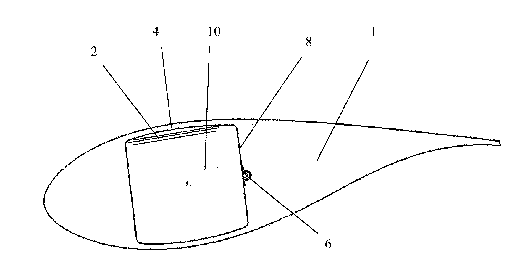
[0020]As shown in FIG. 1, the lightning conduction system in the blade (1) with carbon fiber laminates (2), object of the invention, employs a lightning conduction system based on a primary cable (6) to which, additionally, some bypasses are fitted in order to connect it directly with the carbon fiber laminates (2) thereby ensuring the equipotentiality of both systems.

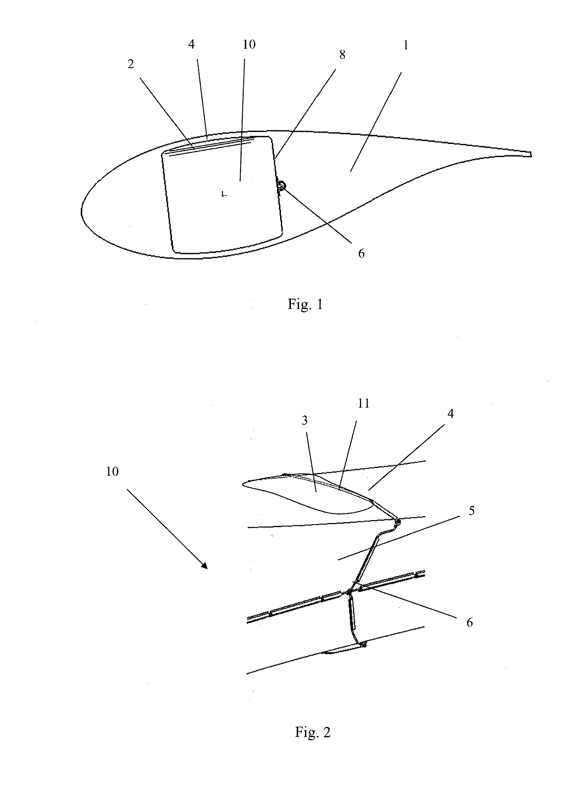
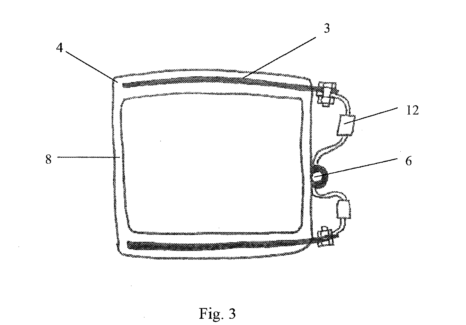
[0021]As shown in FIG. 2, the bypasses are made with two connections to each one of the two carbon fiber laminates (2), the one corresponding to the upper part of the beam (10) and the one corresponding to the lower part of the beam, represented in the previous figure. These laminates are located on the two sides that are affixed to the shells of the blade known as the flanges (4). One connection is made in the beam root area and the other at the tip area so that the flanges (4) of the beam become alternative paths for the bolt. The differentiating characteristic of the system lies in the form that connections are made...


PUM


Abstract

Lightning rod system for wind turbine blades formed by various connections set up on carbon fiber laminates (2) on the blade (1), equipotentializing the surface of the flanges (4) of the beam (10) through the deviations of a primary cable (6) with the respective auxiliary cables (5), carried out with the use of a device (12) whose terminals are connected between the ends of the cited auxiliary cable (5).The use, given the elevated inductance of device (12) mounted on the connection between the carbon laminates (2) and the conductor cable or primary cable (6), is to reduce the passage of current across the carbon laminate and favor the conduction through the metal cable.

Description

OBJECT OF THE PATENT[0001]The object of the patent is to furnish a lightning conduction system for current wind turbine blades. The new lightning system is achieved by adding a device that reduces the current fraction of the lightning transmitted through the carbon fiber laminates.BACKGROUND OF THE INVENTION[0002]Given the height of the wind turbines and their erection in elevated regions lacking other elements having similar heights, there is a high risk of being struck by lightning, especially in the blades. With this in mind, blades must be equipped with a lightning protection system, and any other additional system installed in the blade containing conductor elements (metal parts, sensors, beacon systems, etc.) must be protected against direct impacts of lightning bolts and indirect effects of the electromagnetic field induced by the bolt current.[0003]The primary components of the lightning protection system for wind turbine blades are a series of metal receptors mounted on the...

Claims


Application Information

Patent Timeline
Patent Type & Authority Applications(United States)
IPC IPC(8): F03D11/00
CPCF03D1/0675F03D11/0033Y02E10/721F05B2280/6003Y02E10/722F05B2280/2006F03D80/30Y02E10/72H02G13/00
Inventor AROCENA DE LA RUA, IONPASCUAL, ENEKO SANZA
Owner GAMESA INNOVATION & TECH SA
Why Eureka
Try Eureka