
Oscillators having arbitrary frequencies and related systems and methods

Active Publication Date: 2012-06-07
ANALOG DEVICES INC
View PDF14 Cites 11 Cited by
  • Summary
  • Abstract
  • Description
  • Claims
  • Application Information

AI Technical Summary

Benefits of technology

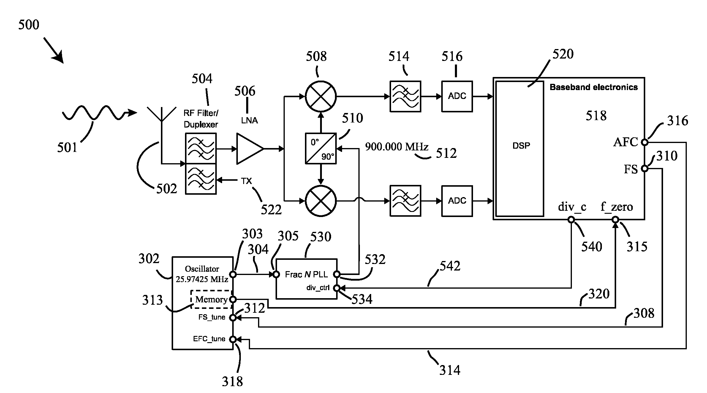
[0017]According to another aspect of the present application, a method is provided. The method comprises measuring a frequency of an oscillating transmitter output signal of a transmitter, the transmitter forming at least part of a transceiver comprising a local oscillator having a mechanical resonating structure. The method further comprises comparing the frequency of the transmitter output signal to a target frequency. The method further comprises

Problems solved by technology

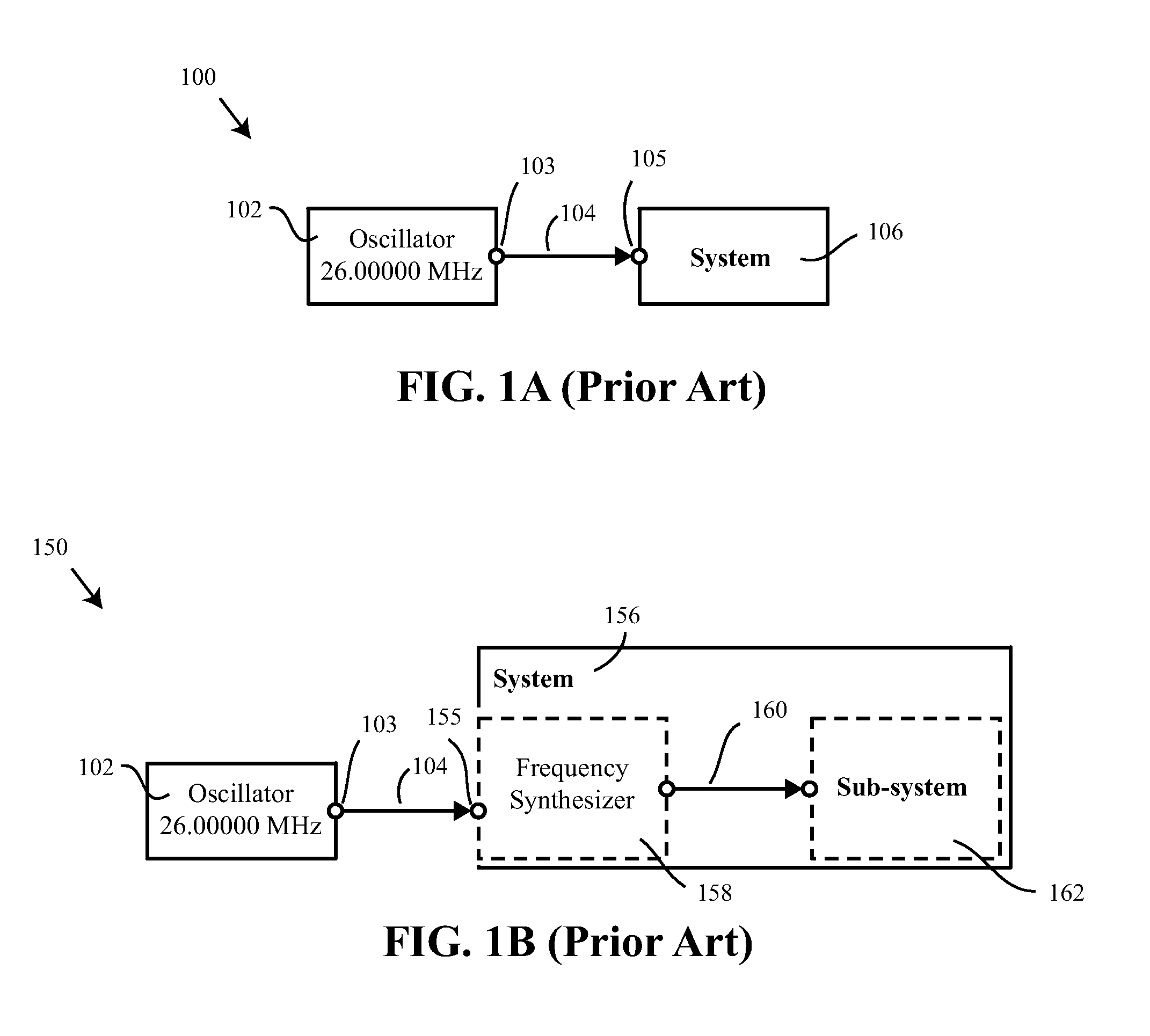
If the system 106 receives a different frequency, it will not operate properly.

Method used


Image

  • Oscillators having arbitrary frequencies and related systems and methods
  • Oscillators having arbitrary frequencies and related systems and methods
  • Oscillators having arbitrary frequencies and related systems and methods

Examples


Embodiment Construction

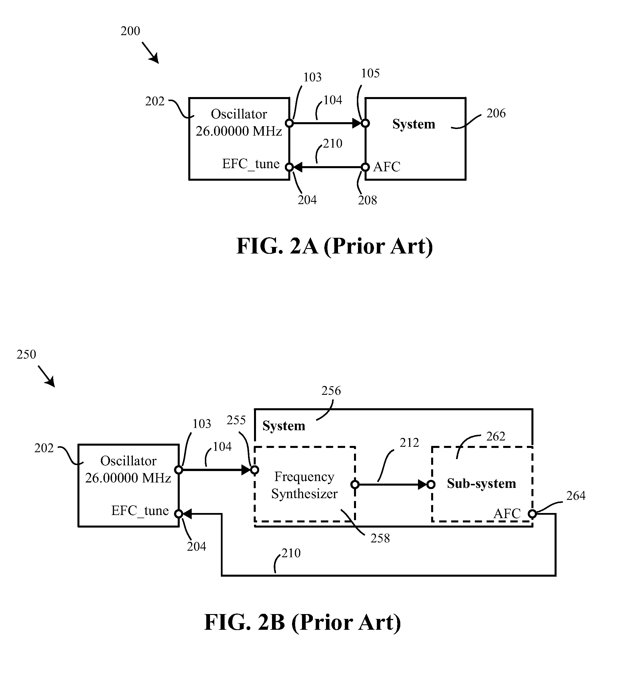
[0037]While, as described above, conventional quartz crystal resonators can be manufactured to provide an oscillating signal of precise frequency, doing so requires significant effort and cost. Accordingly, Applicants have appreciated that the effort and cost associated with manufacturing conventional quartz crystal resonators may be minimized or eliminated by designing systems which may accurately operate in combination with an oscillator manufactured to produce an arbitrary frequency rather than a conventionally accepted (standard) oscillator frequency. As used herein, “arbitrary frequency” refers to a frequency not substantially matching a conventional standard oscillator frequency. For example, the arbitrary frequency may differ by at least 30 parts per million (ppm) from a standard oscillator frequency in some embodiments. In some embodiments, the arbitrary frequency may differ by at least 50 ppm from a standard oscillator frequency, by at least 100 ppm, by at least 200 ppm, by...


PUM


Abstract

Systems and methods for operating with oscillators configured to produce an oscillating signal having an arbitrary frequency are described. The frequency of the oscillating signal may be shifted to remove its arbitrary nature by application of multiple tuning signals or values to the oscillator. Alternatively, the arbitrary frequency may be accommodated by adjusting operation one or more components of a circuit receiving the oscillating signal.

Description

RELATED APPLICATIONS[0001]This application claims the benefit under 35 U.S.C. §120 as a continuation-in-part (CIP) of U.S. patent application Ser. No. 12 / 721,484, filed on Mar. 10, 2010 under Attorney Docket No. G0766.70015US01 and entitled “Oscillators Having Arbitrary Frequencies and Related Systems and Methods,” which application is hereby incorporated herein by reference in its entirety. Patent application Ser. No. 12 / 721,484 in turn claims the benefit under 35 U.S.C. §119(e) of U.S. Provisional Patent Application Ser. No. 61 / 289,984, filed on Dec. 23, 2009 under Attorney Docket No. G0766.70015US00 and entitled “Oscillators Having Arbitrary Frequencies and Related Systems and Methods”, which application is hereby incorporated herein by reference in its entirety.[0002]This application also claims the benefit under 35 U.S.C. §120 as a continuation-in-part (CIP) of U.S. patent application Ser. No. 12 / 721,472, filed on Mar. 10, 2010 under Attorney Docket No. G0766.70015US02 and enti...

Claims


Application Information

Patent Timeline
IPC IPC(8): H03L7/00
CPCH03B5/32H03L7/197H03L7/18H03J7/065
Inventor SCHOEPF, KLAUS JUERGENREBEL, REIMUNDKUYPERS, JAN H.
Owner ANALOG DEVICES INC
Learn More